
Details of part one of the Living Room Project can be seen here.
The old Kitchen at Belle Vue Road had some strange architectural 'features' which had long puzzled me, including what held the load bearing wall on the first floor and why the room had a strange triangular shaped piece of wall sticking into the room.
We made a few holes in the ceiling and didn't like what we saw so decided it was time to build a new kitchen and commence some major internal building work.
We had decided already that we'd like to move the kitchen from the back of the house to the front. The house is on the fairly busy Belle Vue Road, in Shrewsbury. The traffic noise at the front of the house can be a bit loud. During a previous project, after acquiring the land behind the house, putting in French doors and building a deck, we had decided it would be a really good idea to have the living room at the back of the house as we could could enjoy the peace and quiet and the view out over the deck and garden more from here.
Building a new kitchen made sense too because it gave us a chance to put in the new kitchen, a new boiler and a heating system before we took out the old one as we weren't in a position to vacate the property while we carried out the refurbishment.
A planned break between contracts meant that I could work full time on the refurbishment work and look after the majority of the work myself. There were a couple of areas where I have subcontracted the work; namely the work to dig out the old floors (highly labour intensive and requiring a lot of muscle) and the jobs of plastering and tiling where the level of skill required is beyond my time scale to acquire.
Below are a few photo's of the new kitchen going in, starting with putting in the new sewer and fresh water connections. I went off and undertook UK WRAS training and am now certified to make the mains water connections.
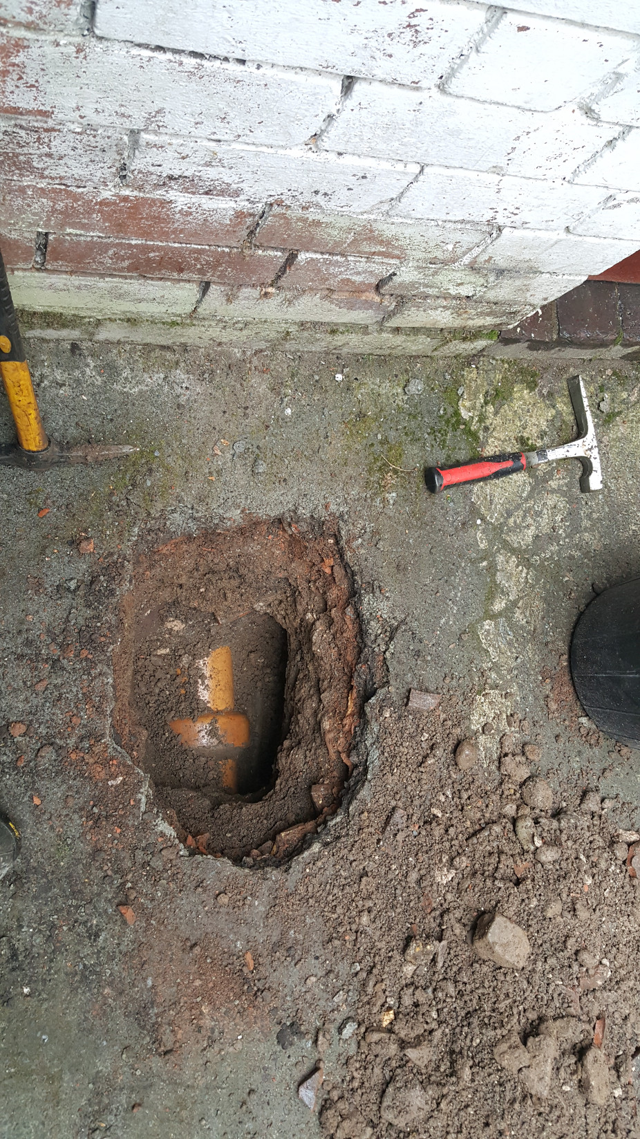
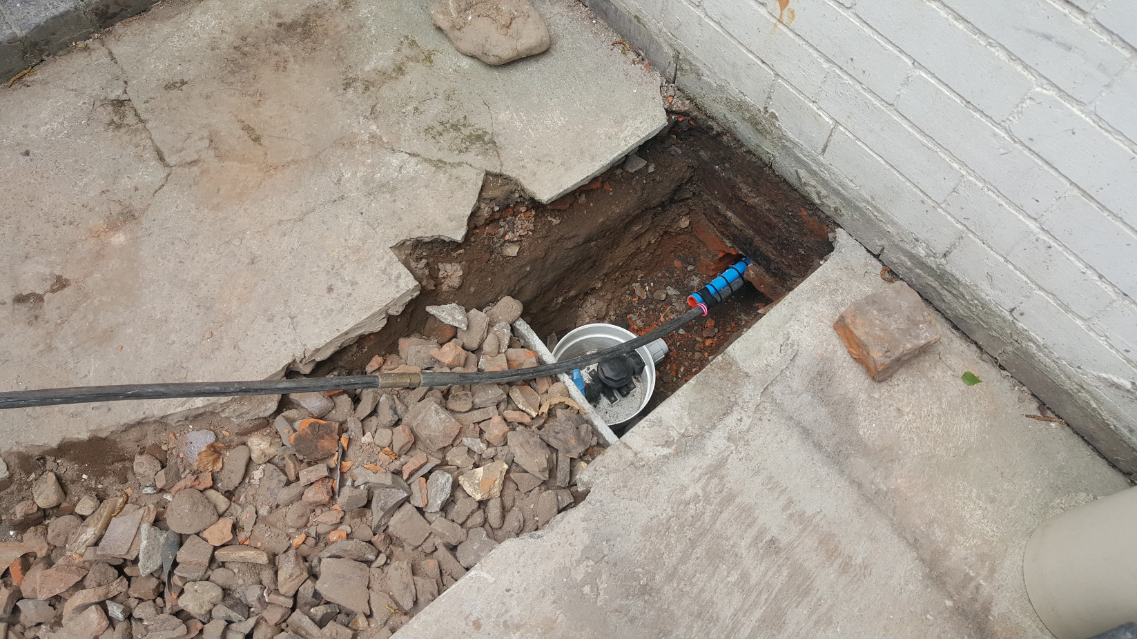
In order to provide drainage for the new kitchen (for the sink, the dishwasher and the washing machine) it was necessary to dig down to, and break into the, the existing sewer pipe alongside the house. The is excavation was made a little more difficult for two reasons; firstly there was limited access as the sewer ran down an alleyway at the side of the house and secondly, we didn't want to cause any damage to the existing pipework due to the digging.
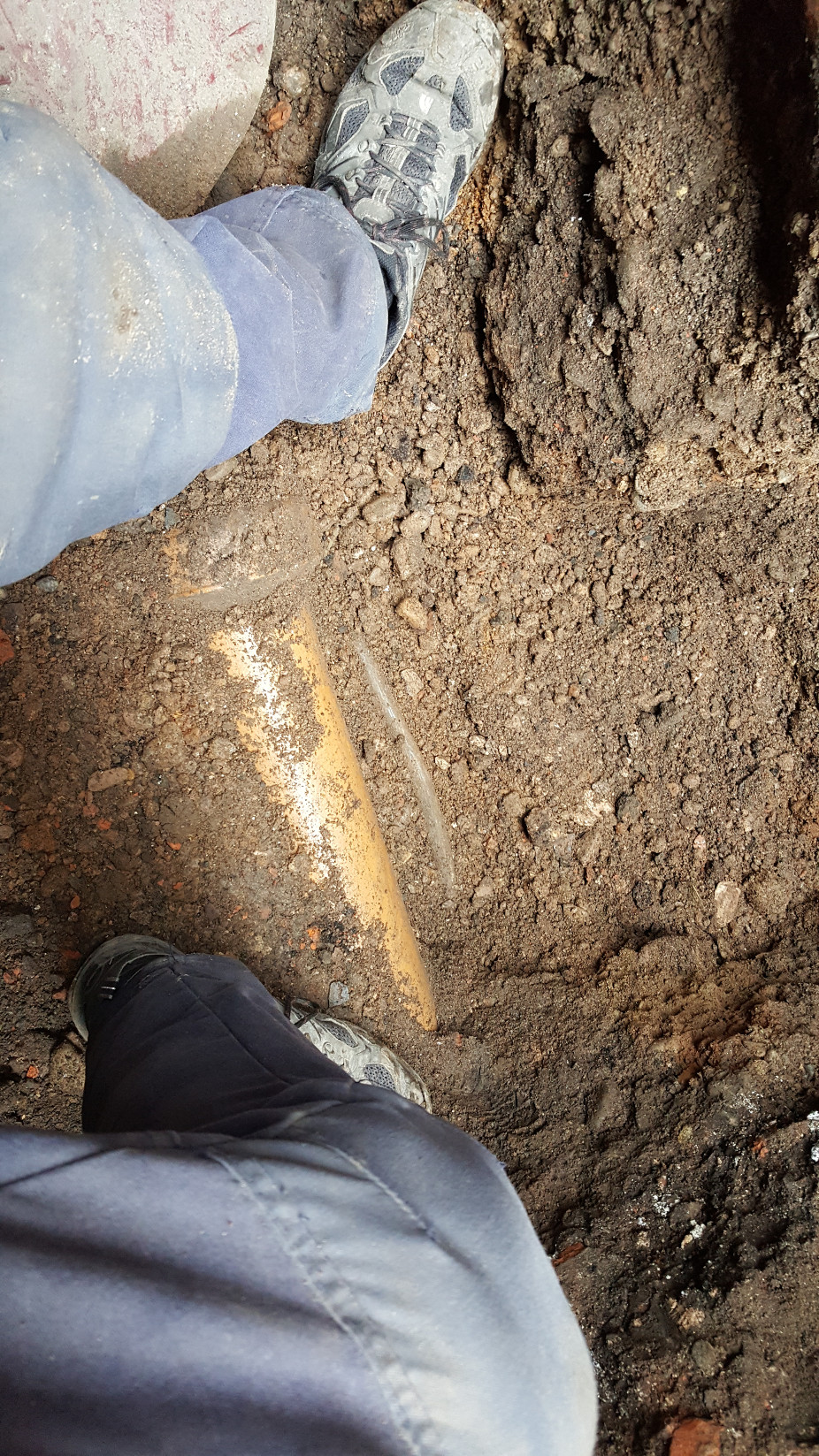
As it transpired the caution was rewarded as we found the water main, buried alongside the soil (sewer) pipe. This makes senses as the original Plumbers would have dug one trench and run the soil pipes and the fresh water pipes in the same trench. Plumbers is the accurate name for them: the water main is run in from the street in 7lb, 1/2" Lead pipe. The cold water main is the grey pipe next to the yellow coloured soil pipe (which is Salt Glazed Ceramic pipe)
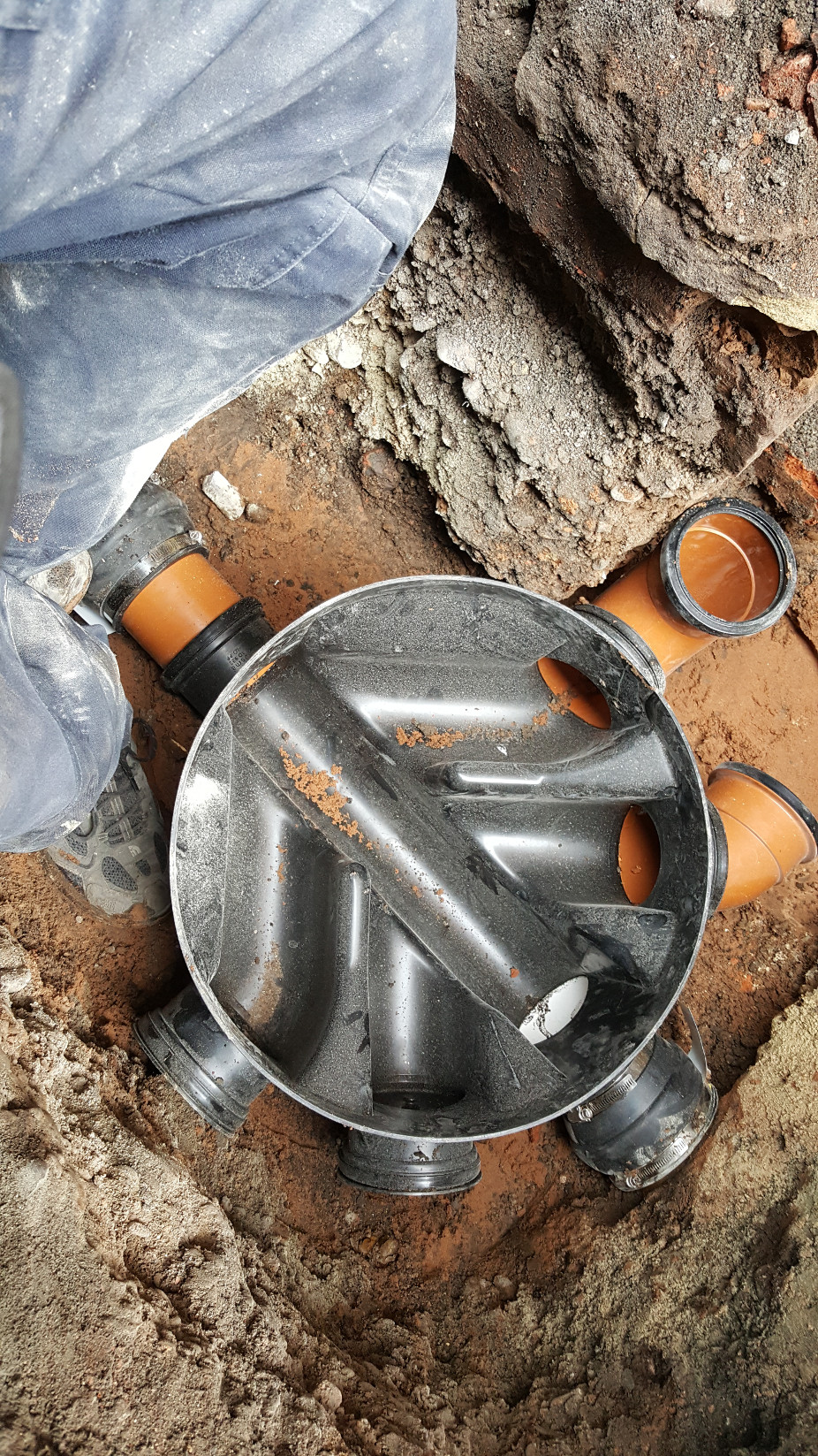
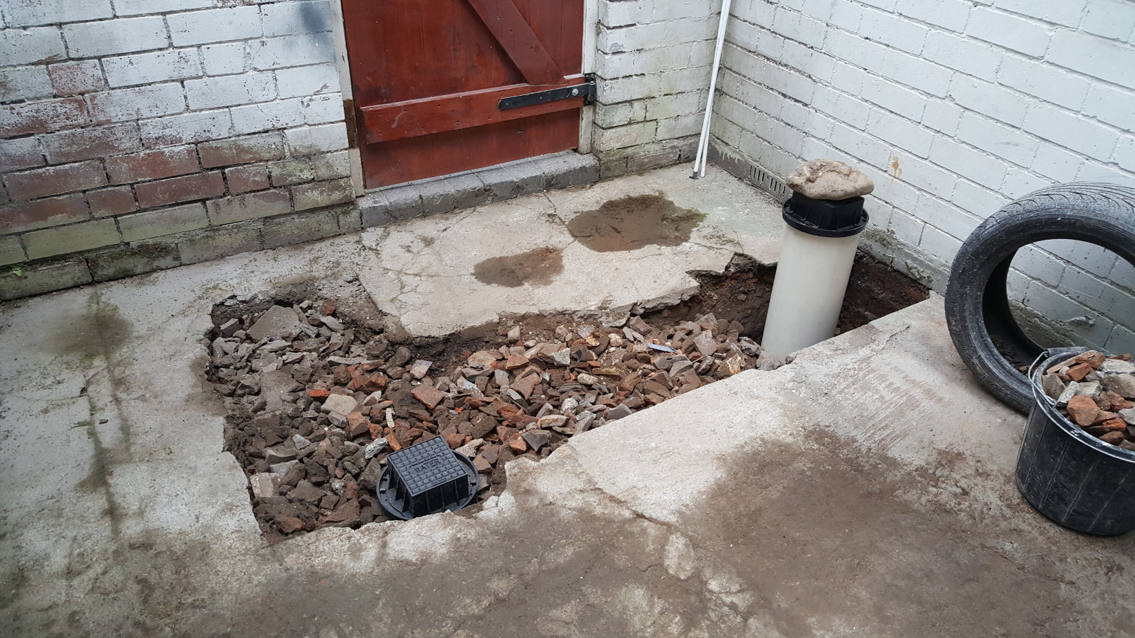
The modern equivalent of the Salt Glazed pipework is plastic (thankfully) and this is much lighter, more versatile and much easier to install, though not cheap. To put in this chamber, the riser rings and the man hole cover cost over £350 in materials alone. Underground plumbing isn't cheap!
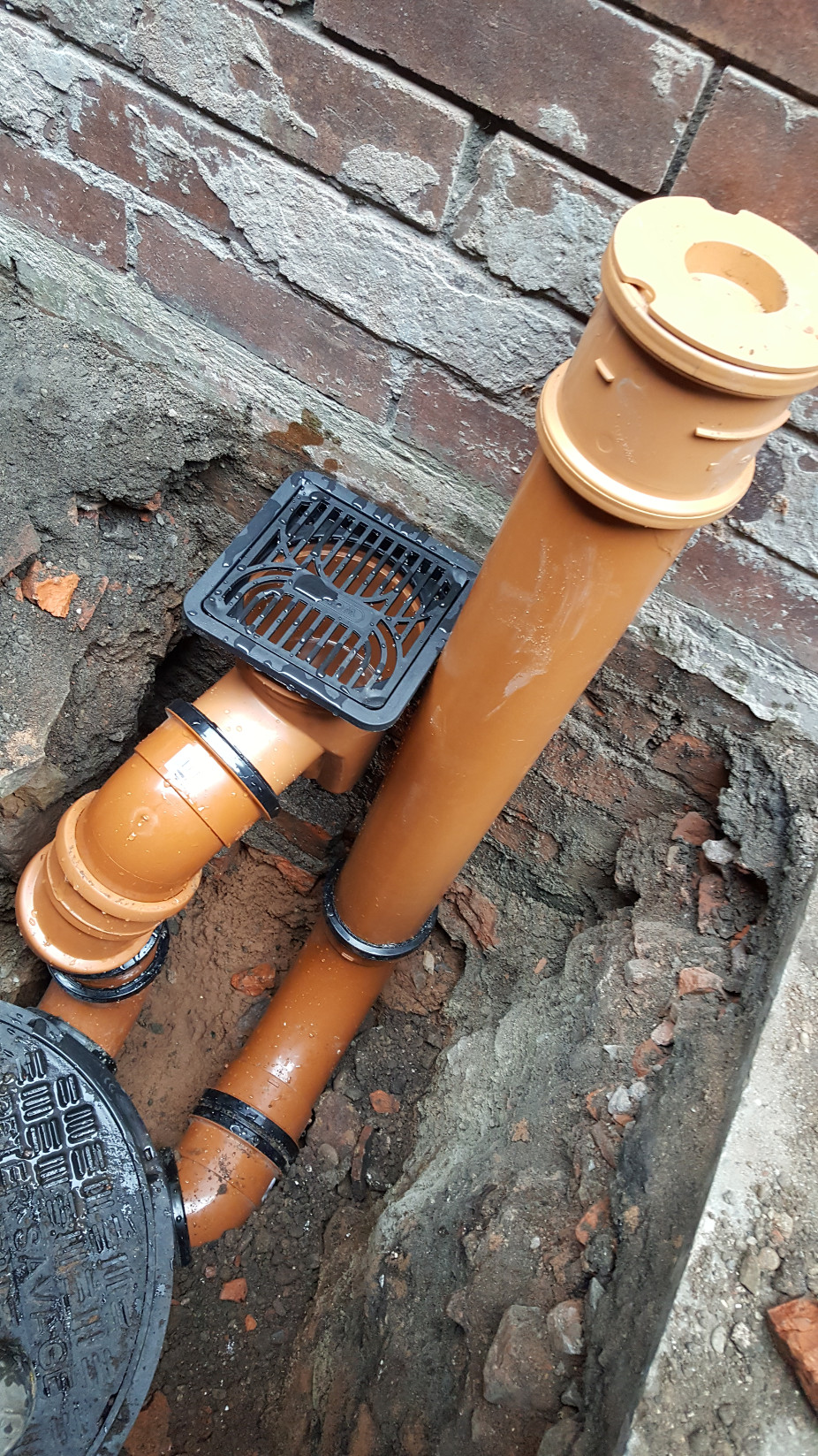
View showing the rodable bottle trap with grating (for draining rain water from the alleyway) and the capped off pipe which we'll use for the kitchen connections (managerial decision; Julie didn't want an open grid for the kitchen wastes as she didn't want to see odd bits of vegetable from dishwashing in the alley when she pushed her bike out to the road in the mornings...)
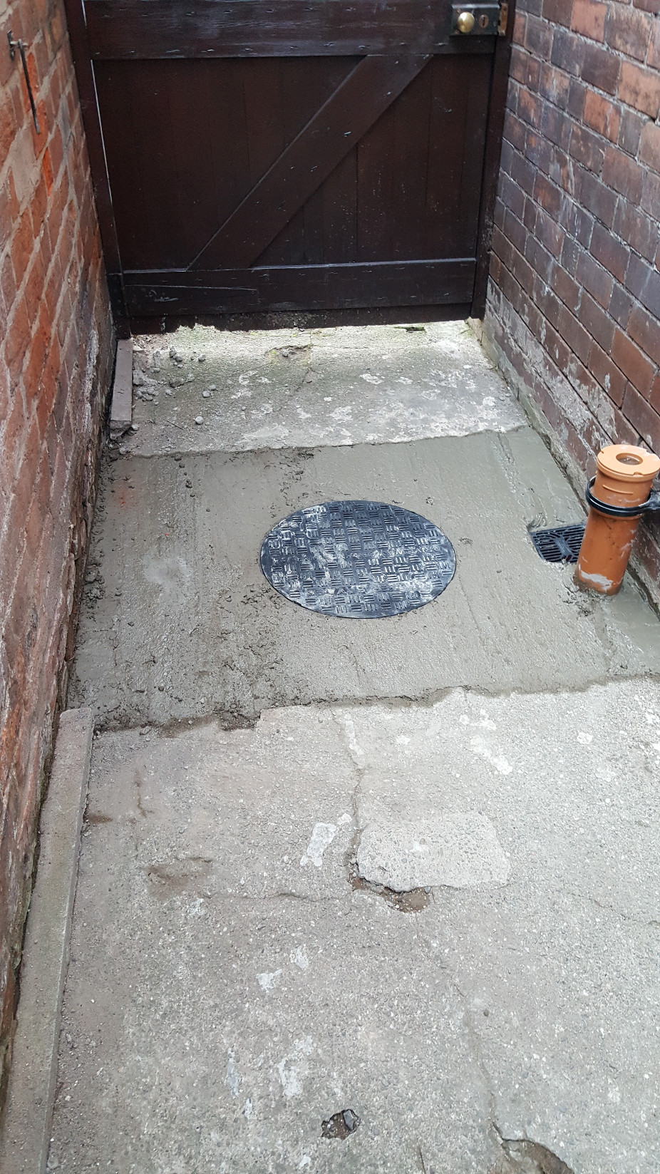
Back filled and concreted in. We're going to dig up the top of this pathway in the future to re-pave it so the concrete around the manhole is only about 60mm thick but the risers (the tubes that extend up from the chamber to the manhole cover) are well packed in with crushed rubble and pea shingle..
Having found the location of the cold water main it was a simple task to figure out its route into the house (we knew where the stop tap was in the old kitchen) and to dig down for it again in the yard, near where we wanted to feed the new water supply into the new kitchen.
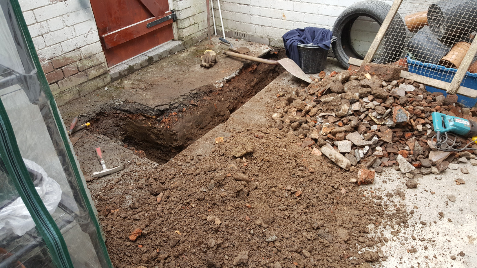
Digging the trenches for the new water connection.
As can be seen there is a lot of stone (crushed rubble) around the house. This is from the house which stood on the site previous to our house being built. Our house is around 120 years old, and was built by the Great Western Railway for one of their drivers (so I'm told). This house and the one next door are built of much better materials than the houses either side, the facing bricks are very dense and very hard and roof is straight with no signs of sagging after all this time. The crushed rubble that we have dug up is much the same as the brick work of the houses around us. Some of the old materials have been used on the interior walls of the house but much has been used as hard-core around the building. Recycling is not new...
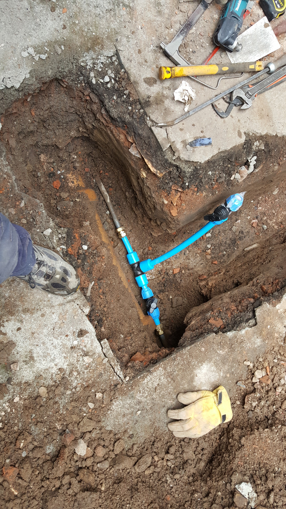
Making the T connection into the existing lead water main: We've cut out a section of lead pipe and used Leadlock fittings to connect the 25mm poly pipe. There are two stop taps installed as the pipe going toward the bottom of the picture goes to the original water connection into the house and is required for the first part of the project. We later connected this same line to the outside tap after the origininal, inside, stop tap was removed. The second stop tap will be the main stop tap for the new water connection into the house when the new boiler and kitchen are commissioned.
More back filling. The second stop tap riser has still to be cut to length, at present, out of shot, there is a board holding the rubble back from the riser and the house wall as the pipe going into the house has yet to be fitted and connected to the outlet of the stop tap.
Pulling the water main out of the house to the stop tap. I fitted very heavy gauge underground pipe insulation to the pipe and taped it securely in place with electrical tape. The pipe runs in a floor void which is ventilated and the insulation is to prevent any chance of the pipe freezing. We had thought about fitting a trace heating tape (a self regulating electrical heating tape) to the pipe but this brings other problems with it and my WRAS training told me that it wasn't necessary to do more than insulate the pipe properly. This end of the pipe seen here is buried and doesn't require insulation.
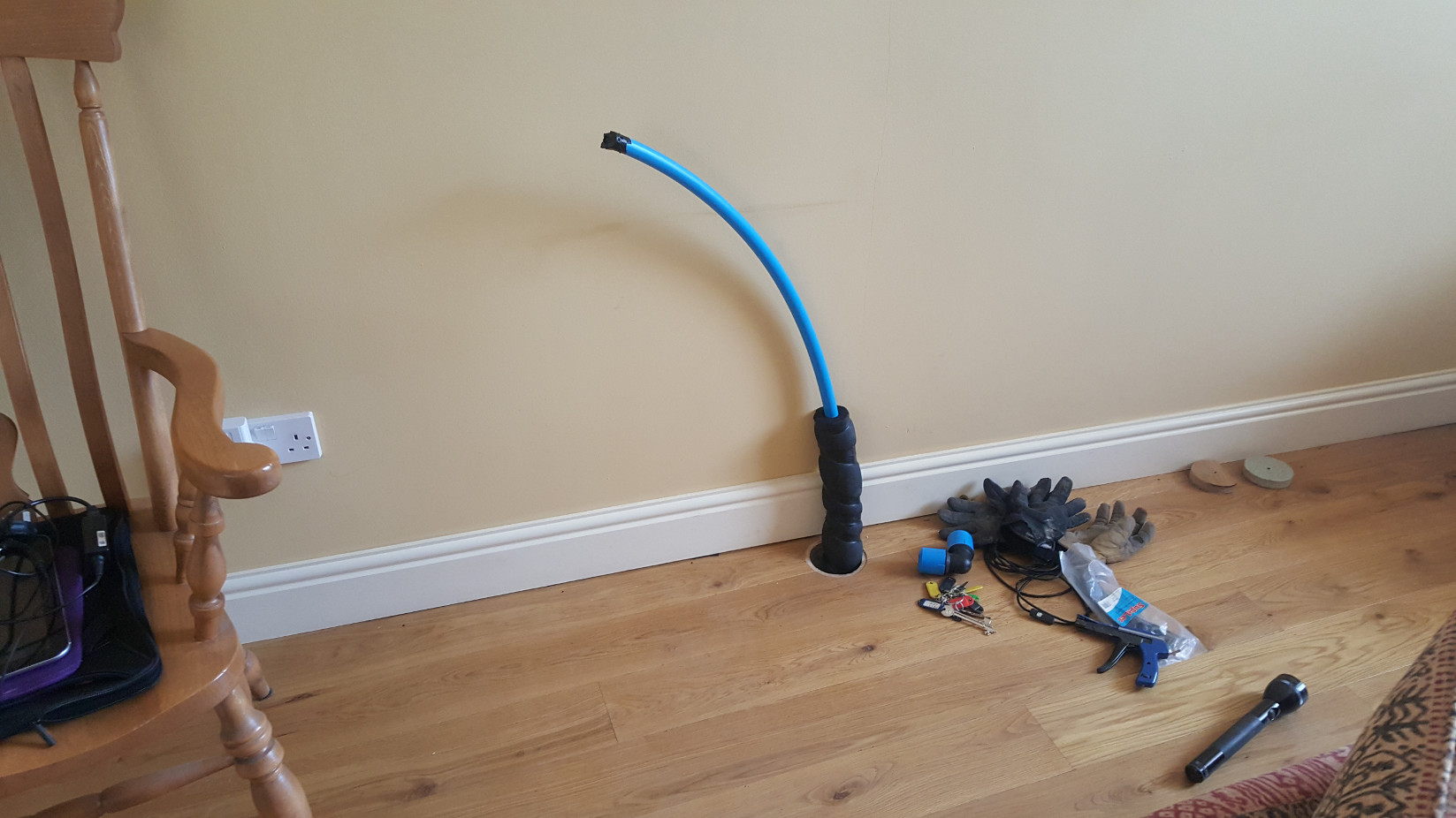
The other end of the pipe, where it enters the building. This will be behind the sink once the kitchen is installed.
Once I'd completed connecting the mains water inside and the pipework was fixed to the wall, I placed a polythene bag into the hole, around the pipe, and filled it with expanding foam. Once the foam had set I carefully trimmed it flush with the floor. The purpose of this was to create an draught proof seal around the pipe.
Next came the work inside the house on the kitchen. There were several strands to this work, rewiring the room to suit the new kitchen layout, installing the new boiler and associated pipework and installing the kitchen units. Below are some of the photos:
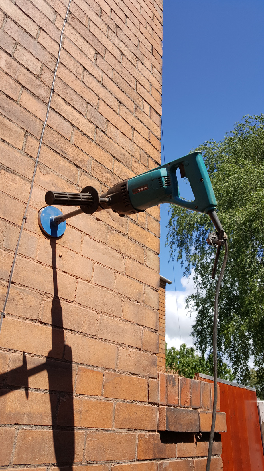
A beautiful sunny day, ideal for being outside for an hour core drilling the hole for the boiler flue. I use a lot of Makita tools because they are superb quality and are made just down the road from us so service and support is excellent.
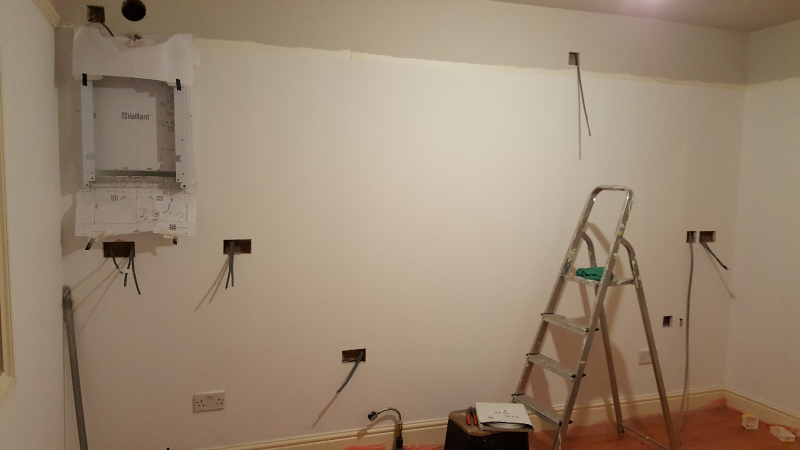
New cables pulled, ready for dry lining boxes to be fitted. The boiler stand off frame is also fitted, over the top of the boiler installation template. We used a stand off bracket as it allowed us to run the boiler pipework behind the boiler for a tidy installation. There is a pressure gauge fitted to the end of the new water feed. We have pressurised the pipework (Mains water pressure) and shut off the new stop tap in the yard. This allows us to check the pipe, which runs under the floor, for any damage before we finally back fill the connection in the yard.
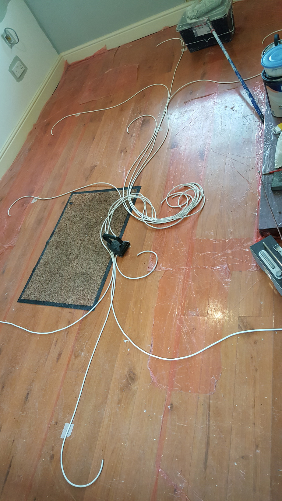
Laying out the wires for the new lighting: we'd put pieces of tape on the floor in the approximate locations where we wanted the down lighters to be on the ceiling and laid out wire, with a bit spare, for each of the downlighters. All of the wires go back to a common junction box which will be located in the ceiling void.
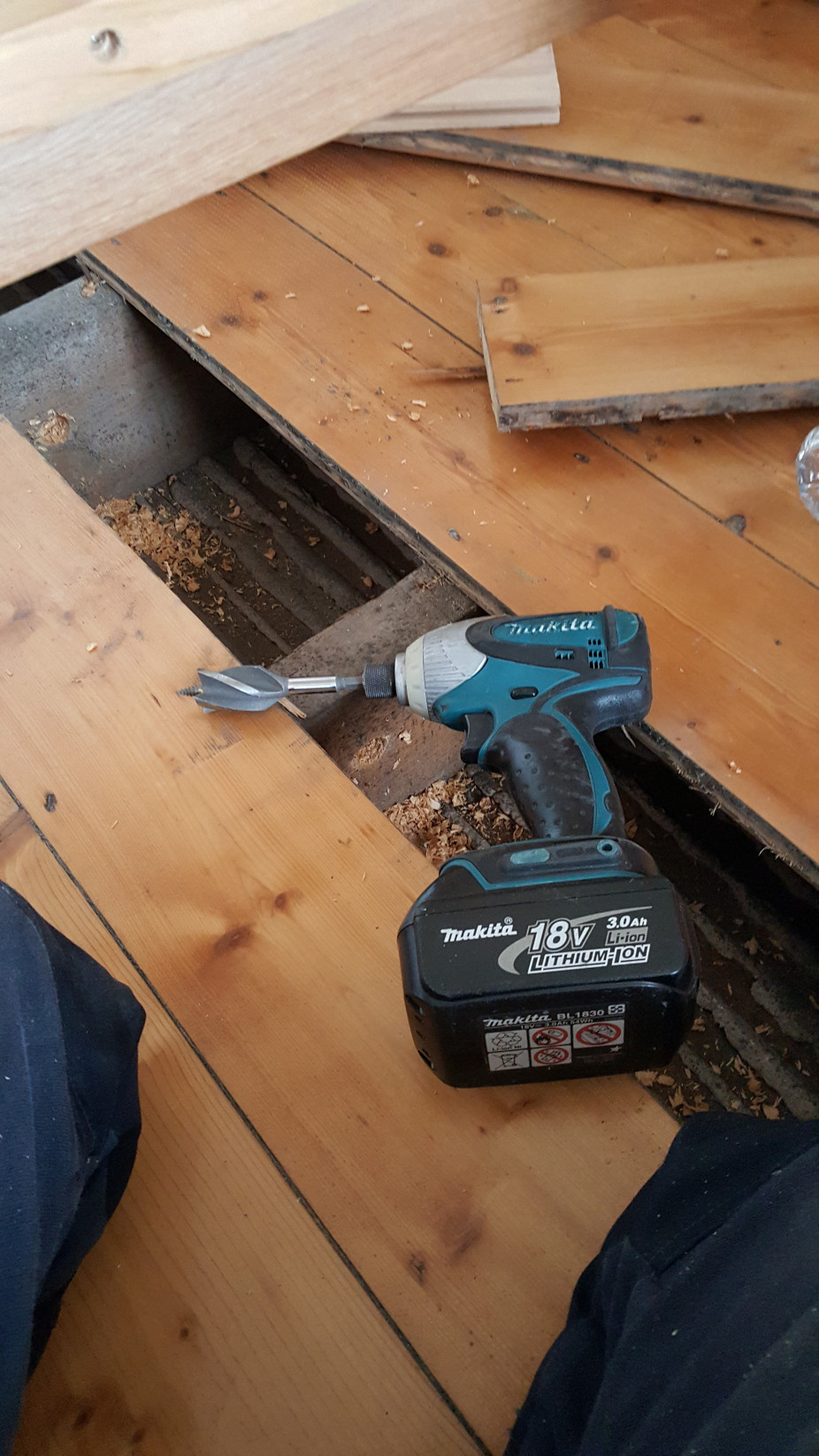
More Makita tools, this time an impact driver with an Armeg 'Wood Beaver Nail Proof' bit fitted. This combination made short, easy work of drilling the cable holes through the 7" x 2.5" pitch pine joists. The ceiling of the room below (the kitchen) has already been over boarded with 12.5mm plaster board over the original lath and plaster ceiling so does not require further boarding for the prevention of the spread of fire. The laths are in good condition but make cutting the holes for the down lighters a little more difficult and it helps to have a really sharp hole saw.
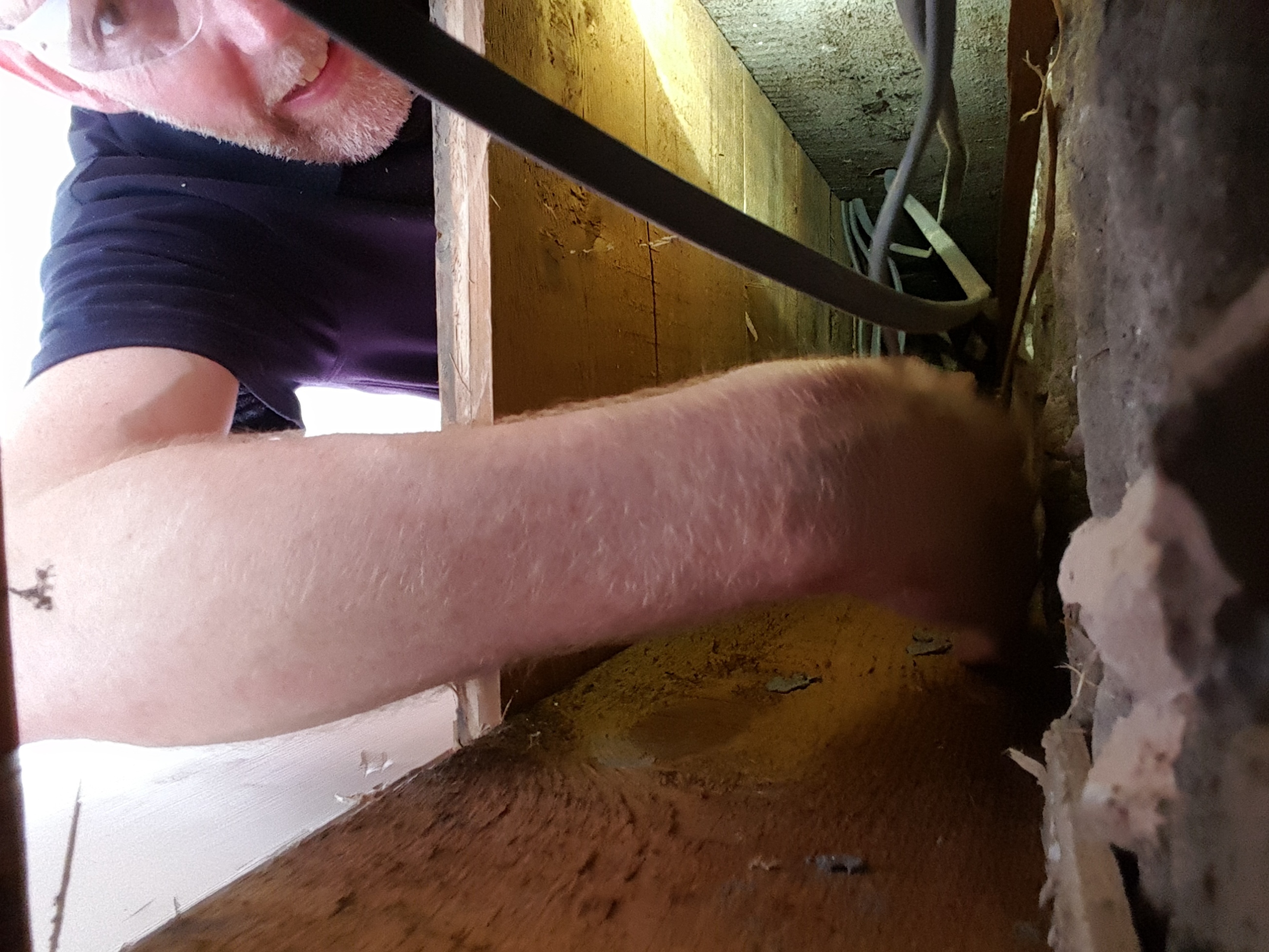
The inevitable groping around in the ceiling void to identify wires and pull in new ones. During the alterations for the wiring for the new kitchen we also to the opportunity to add additional sockets in the bed room above and to remove a couple of incorrectly installed sockets (spurs of off spurs). This additional work allowed us to remove and / or re-route the cables that can be seen going through notches at the top of the joists. We've left it so that all cables / wires run though holes on the centre line of the joist unless there was an existing hole already in place (like the one in the photo above).
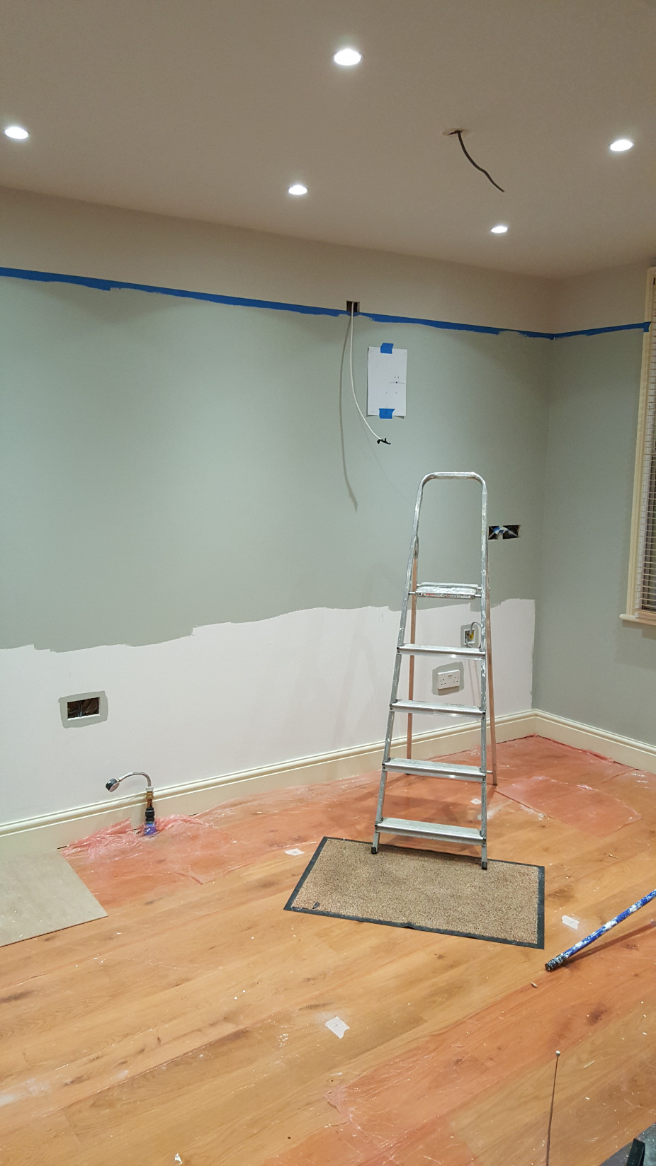
Decorated, lights installed and most of the wiring in place. The piece of paper on the wall is the installation template for the cooker hood, another 100mm diameter core to drill...
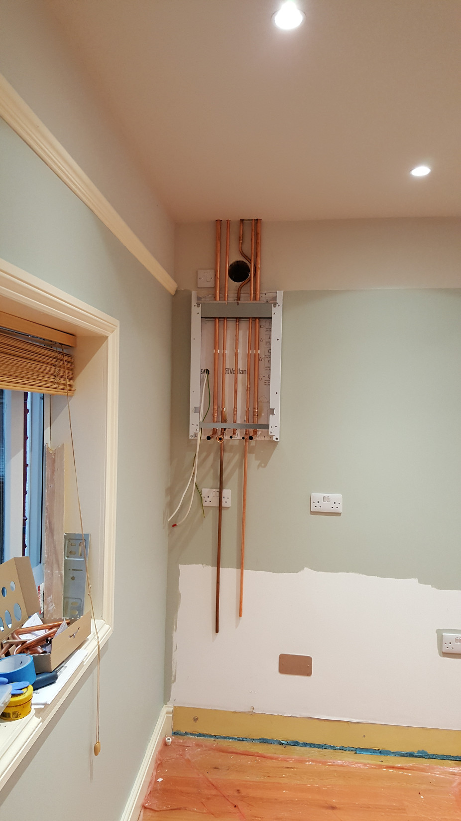
Boiler pipe work. The two pipes running down are the cold water feed to the boiler and the hot water feed which will go to the taps on the kitchen sink. The pipes will be run close together, along side the condensate drain pipe when that is installed so the socket will not have a pipe running across it when we're finished.
The boiler power supply is fed from the switched fused spur off the kitchen ring main, the two flexible cables on the left of the installation frame are the power feed to the boiler and the heat demand cable from the under floor heating system. The power for the wet underfloor heating system is also fed from the boiler supply meaning that switching off the supply to the boiler also cuts power to the under floor heating system.
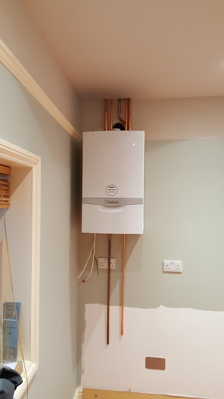
The boiler, hung on the wall, pipework connected. We pressure tested all of the pipework prior to hanging the boiler on to the support frame.
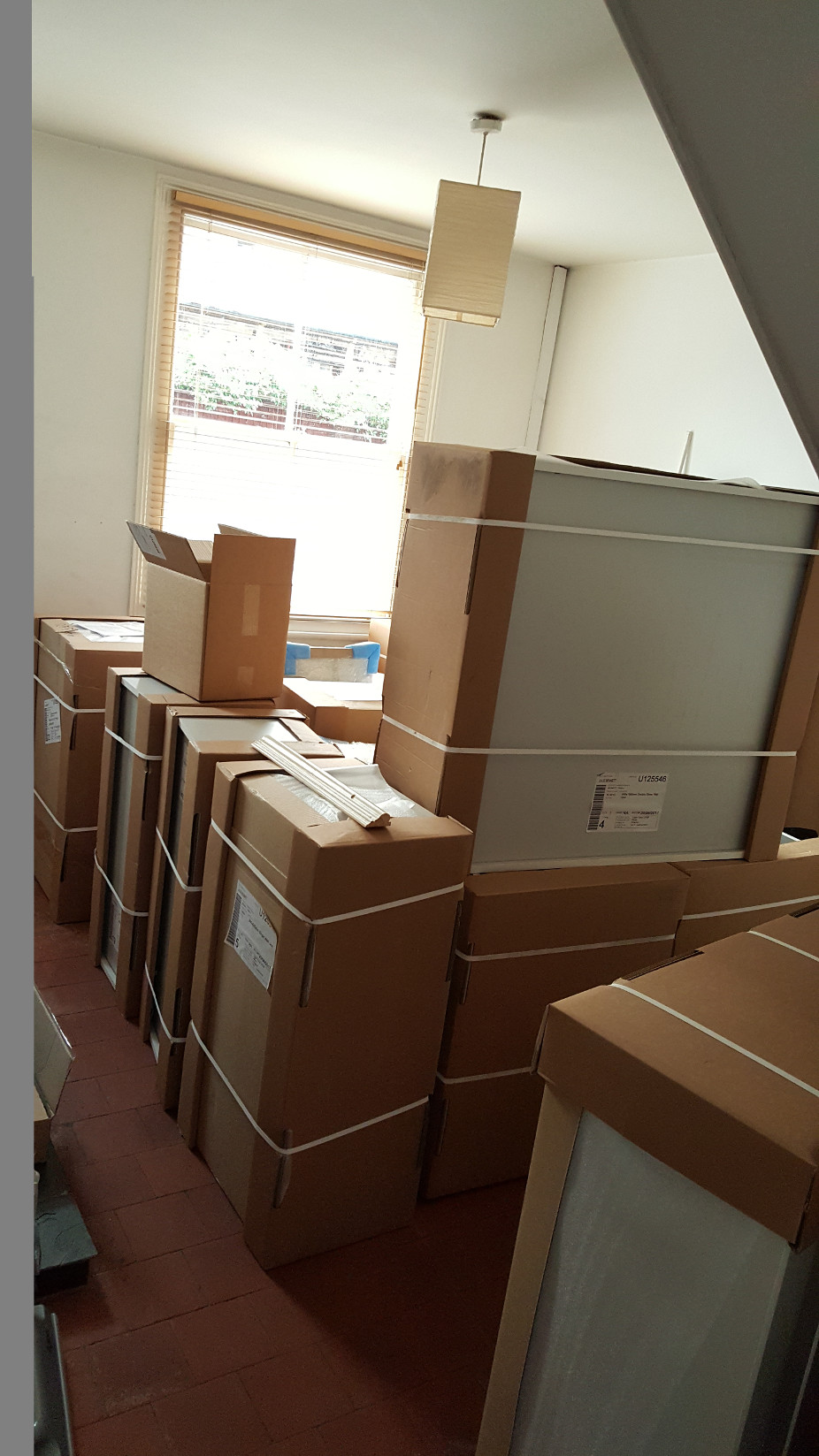
The day the kitchen arrived. The kitchen was supplied by DIYKitchens.com and we went to Pontefract, Yorkshire, to visit the show rooms and to collect loads of samples (we did this on the way back from a very pleasant weekend in York, got to combine business with pleasure where you can!)
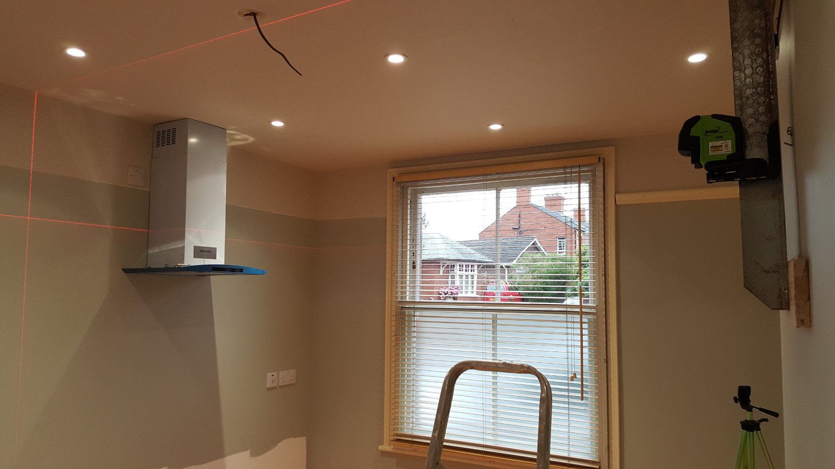
Cross line laser hanging from the wall, ready to start fitting the cupboards. Cooker hood already installed, this job went so quickly (apart from another hour with the core drill. Subsequent to installing and running the cooker hood for a few months I realised that even though the cooker hood was supplied with a 100mm pipe adaptor, that it actually required a much larger diameter outlet to work effectively so I ended up spending a few more hours with the core drill installing a larger diameter outlet) that I didn't get the chance to photograph anything.
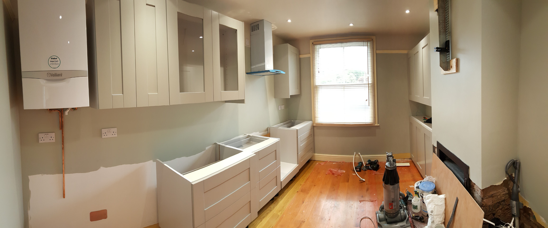
Cupboards hung, base units ready for levelling. Because the walls in this room are dry lined, i.e., plaster board glued onto the brick, there is a void behind the plaster boards. In order to ensure secure fixing of the boiler and cupboards to the walls we've drilled through the plasterboard and all of our fixings go into the brick. We've used hard plastic spacers so that the clamping load of the fixings is transferred to the walls, not directly to the plaster board.
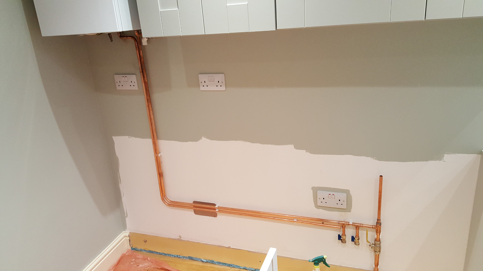
More plumbing, cold water rising main with feed to the boiler and two connectors for the washing machine and the dishwasher. The twin socket is for the power for the washing machine and dishwasher. The second pipe is the hot water feed to the kitchen tap, waiting for me to do some intricate pipe bending to bring it to the correct point.
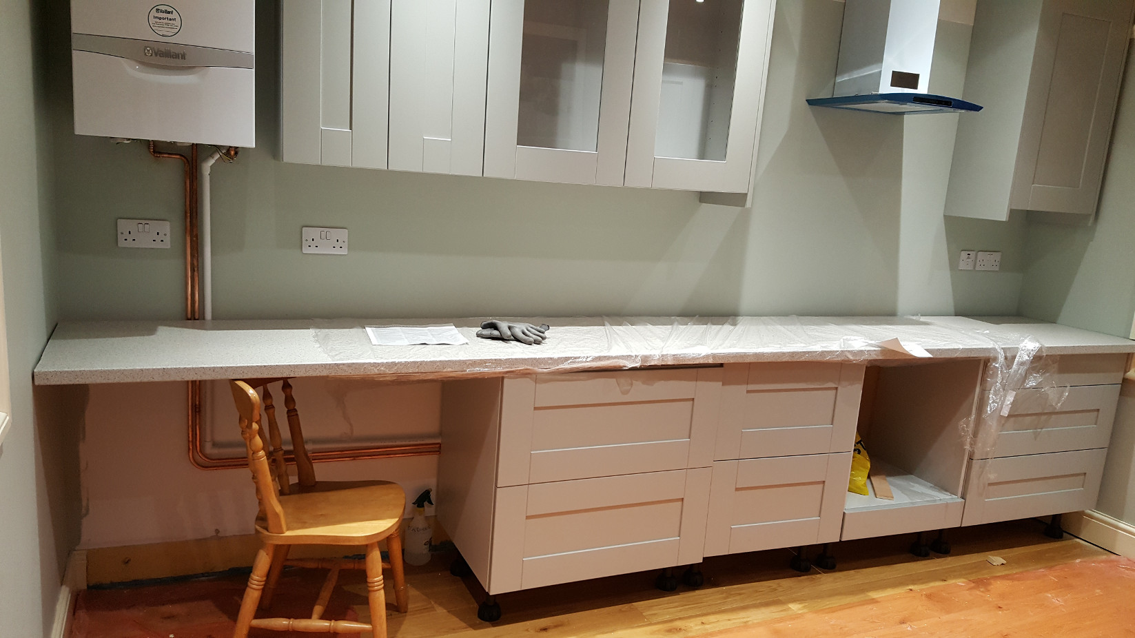
The single piece work top. This had to be cut the day it was delivered because it wasn't possible to fit it in the room otherwise. The top came in through the sash window at the front of the house and hung out of there for ten minutes or so whilst we measured up the correct angle of cut for both ends. The room the new kitchen is in has a taper of around 200mm from the back of the house to the front on the wall the the kitchen work top is going along. This means that at the left hand end of the picture the corner angle is less than 90°, at the right hand end the angle is more than 90°. The chair is under the work top to support this end as there are no brackets fitted to the wall yet. The washing machine and dishwasher will fit under the top so we'll need to support the work top adequately here.
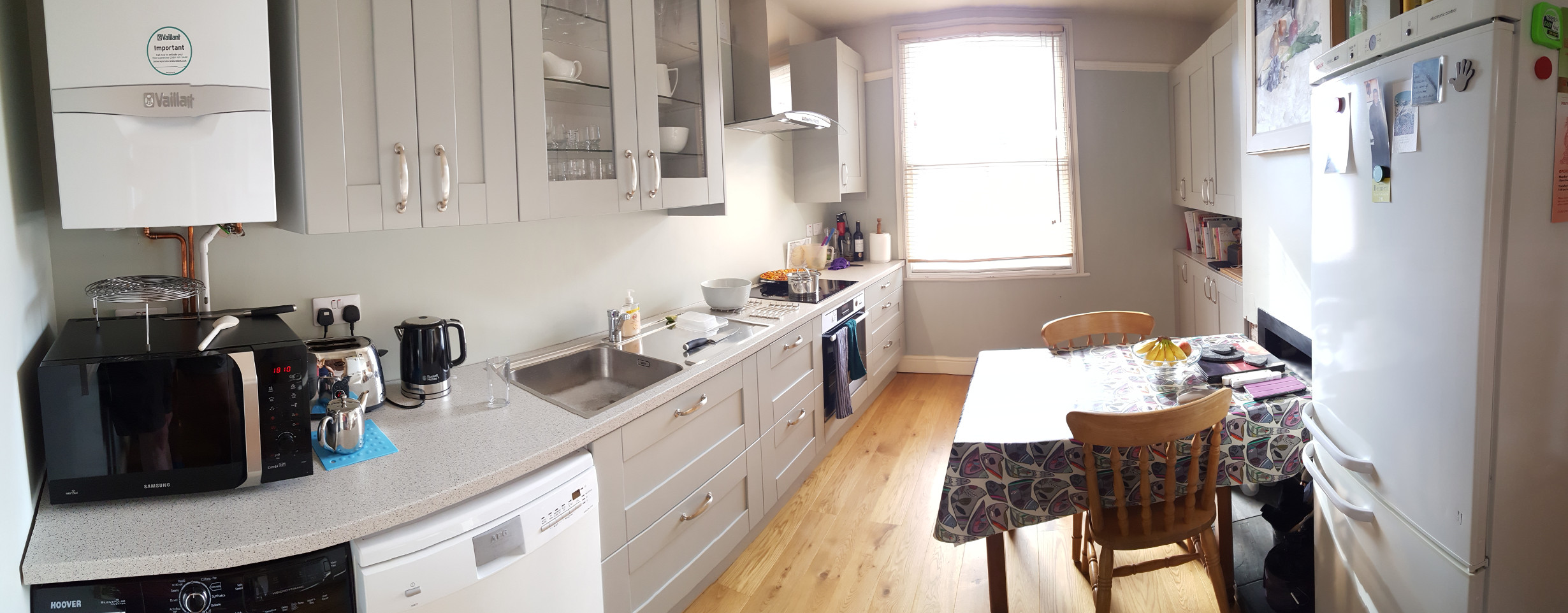
Getting there! The wall behind the work top has yet to be tiled (we're waiting until we have the tiler in to do the floors in the other rooms) but the tiles are hidden away under the base units, waiting.
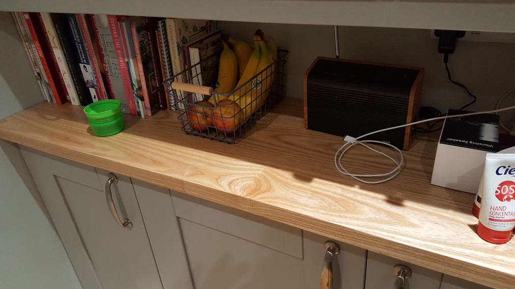
To finish off the small cupboards we decided to have an Ash work top made. Because we chose to use wall cupboards, rather than base units, to fill in the gap next to the chimney breast it would have been costly to buy another section of work top just so that we could throw more than half of it away. The Solid Ash work top cost slight more than another piece of work top but the expense was worth it as this is a lovely feature which complements the Oak flooring.
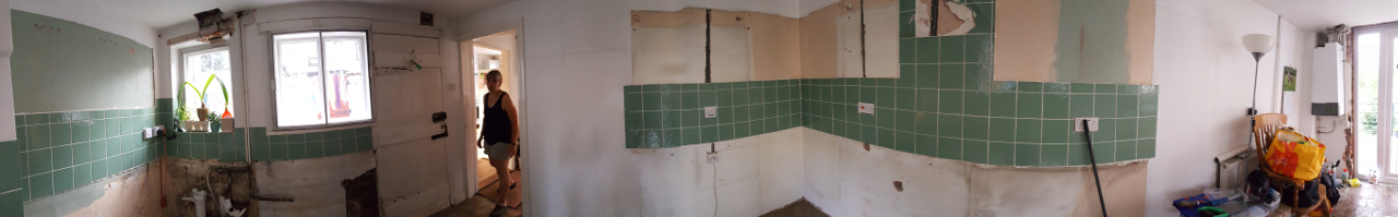
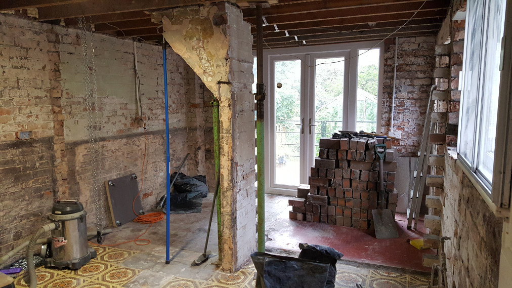
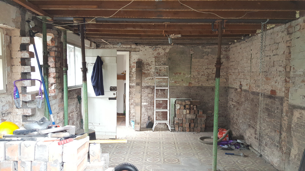
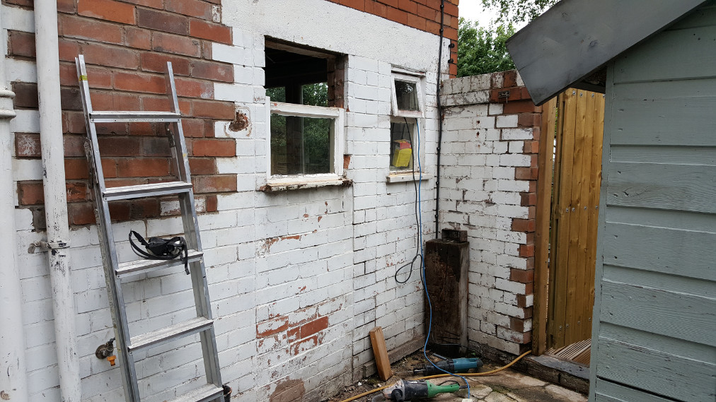
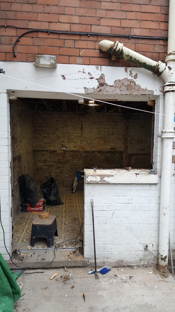
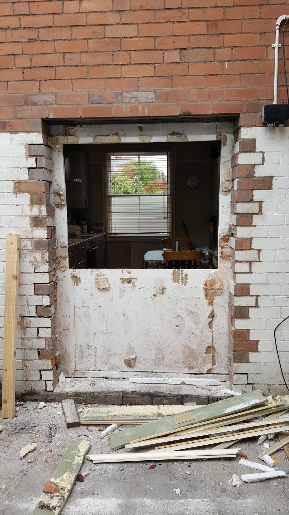
This is a panoramic view of the old kitchen after we'd pulled out all of the old kitchen units. There is damp in some of the exterior wall and the room is very dark due to the low ceiling and the dividing wall.
We found one or two horror stories during the demolition and reconstruction work as you can see below.
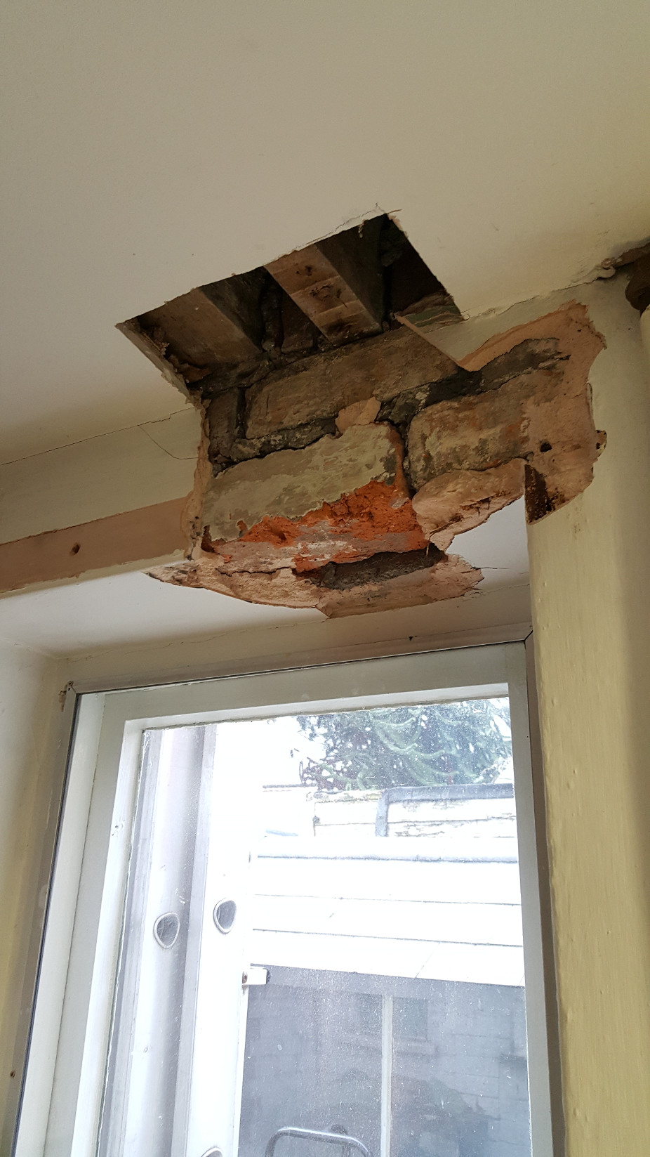
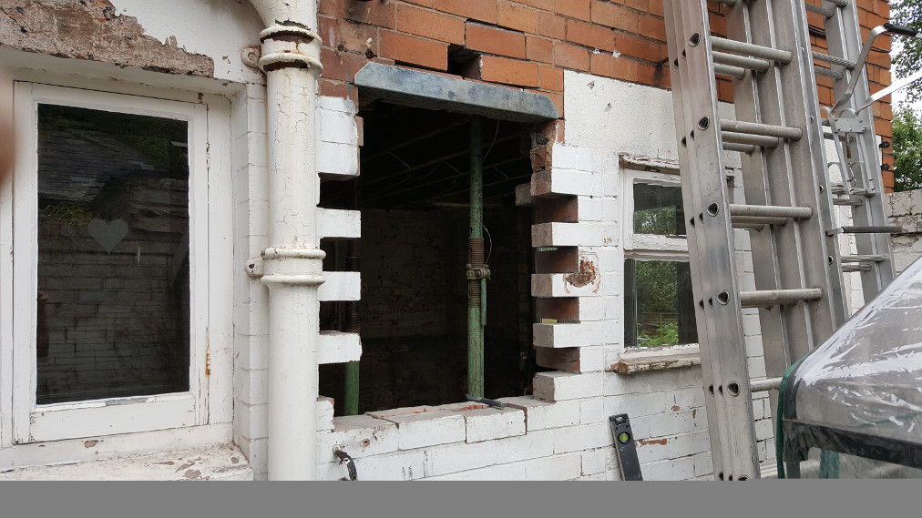
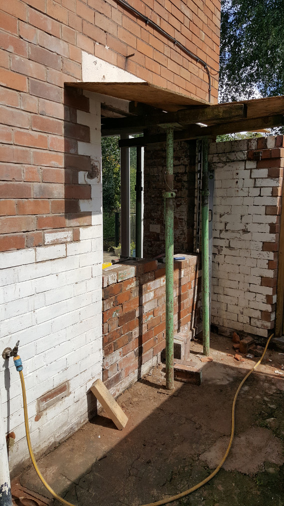
One of the main drivers for the work to take place was that the larger wooden beam, shown in the photo above, carries a load bearing wall which in turn supports part of the roof. At some point in the past (around about 1955 from the newspapers we found in the plaster) someone has decided to make a new window opening and hasn't bothered to provide a lintel to support the beam. That we hadn't seen any cracking in the walls is down to the superior strength of the bricks used and luck!

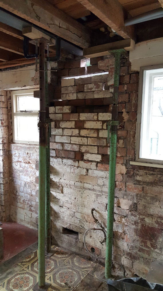
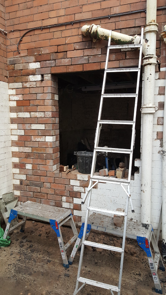
The other end of the horror story: the other end of the heavy beam lands on this slender section of wall (the bit with the ladder leaning on it is non-loadbearing) the triangular section of brickwork extends beyond the beam and supports the far end of the load bearing wall next to a door way on the upper floor. The whole job is a complete bodge and I'm amazed it hasn't fallen down already!
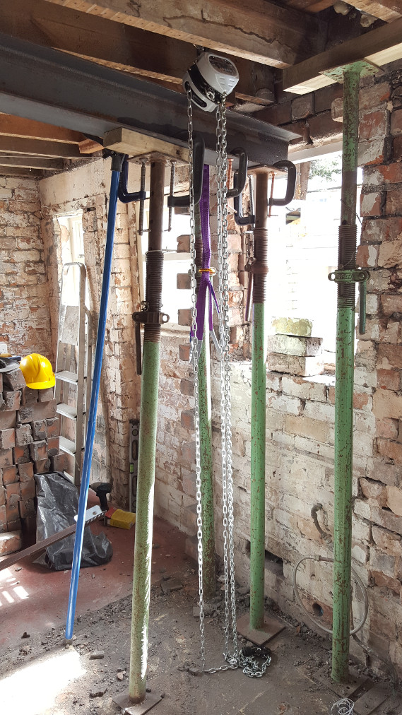
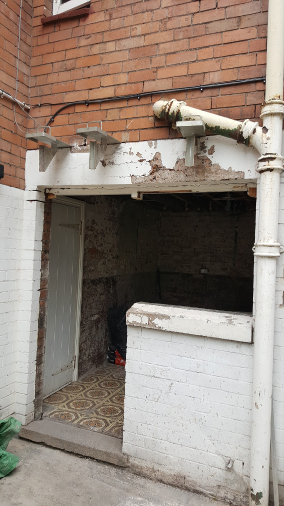
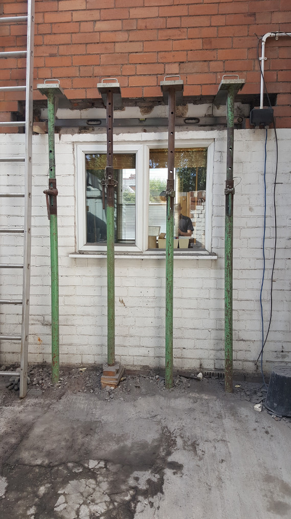
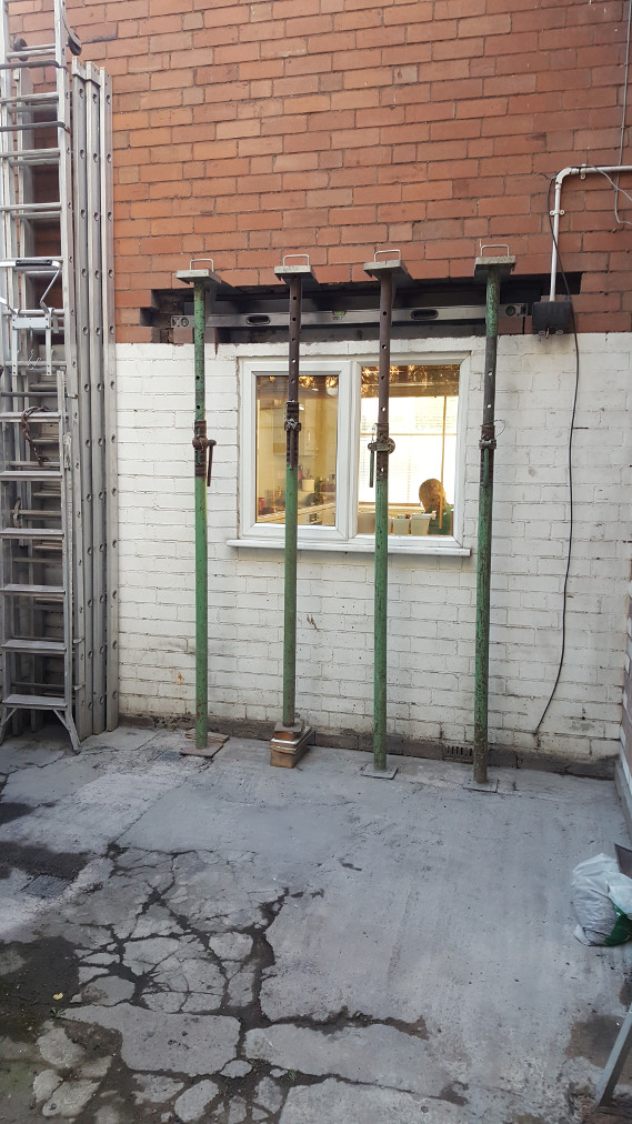
Because of the direction of the joists it wasn't a straight forward job to support the load bearing wall. We made holes through the load bearing wall at floor level on the first floor and then threaded heavy timbers through these holes. The timbers were driven hard against the wall (above them) and the floor (below them) with wedges. This transferred the weight of the wall onto the adjacent joists which were able to support with jacks from below.
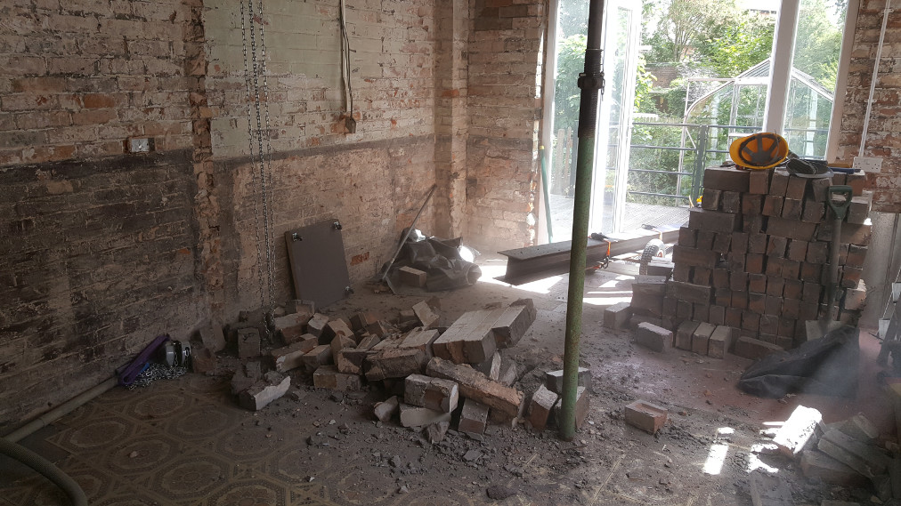
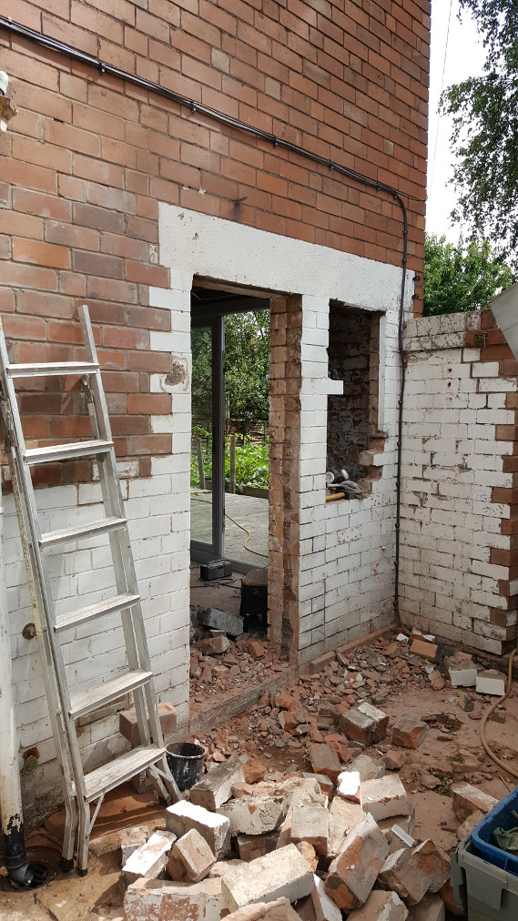
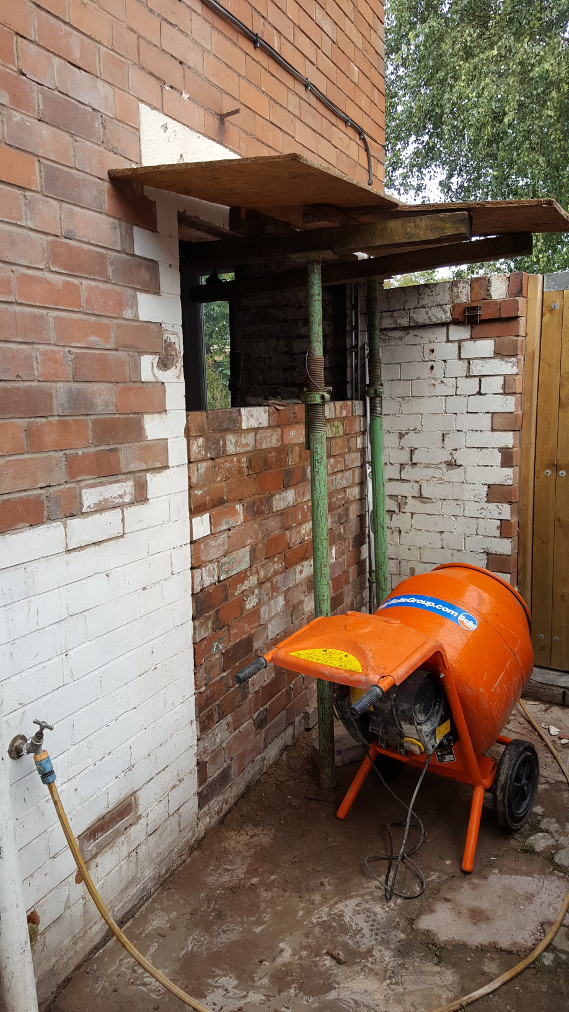
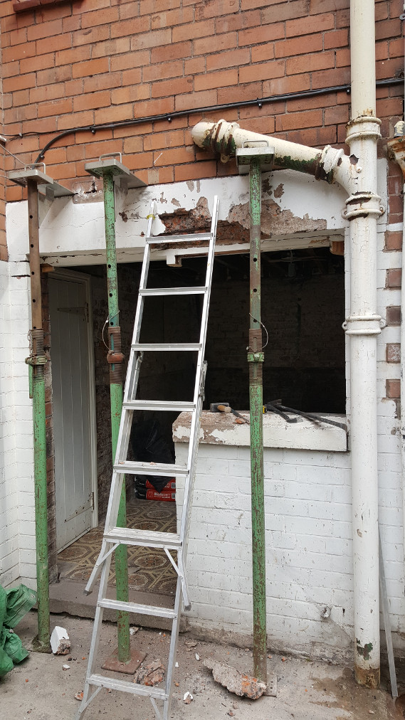
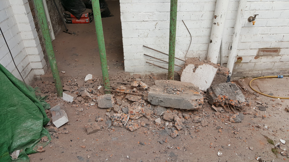
With the load bearing wall supported we started to remove the brick work below.
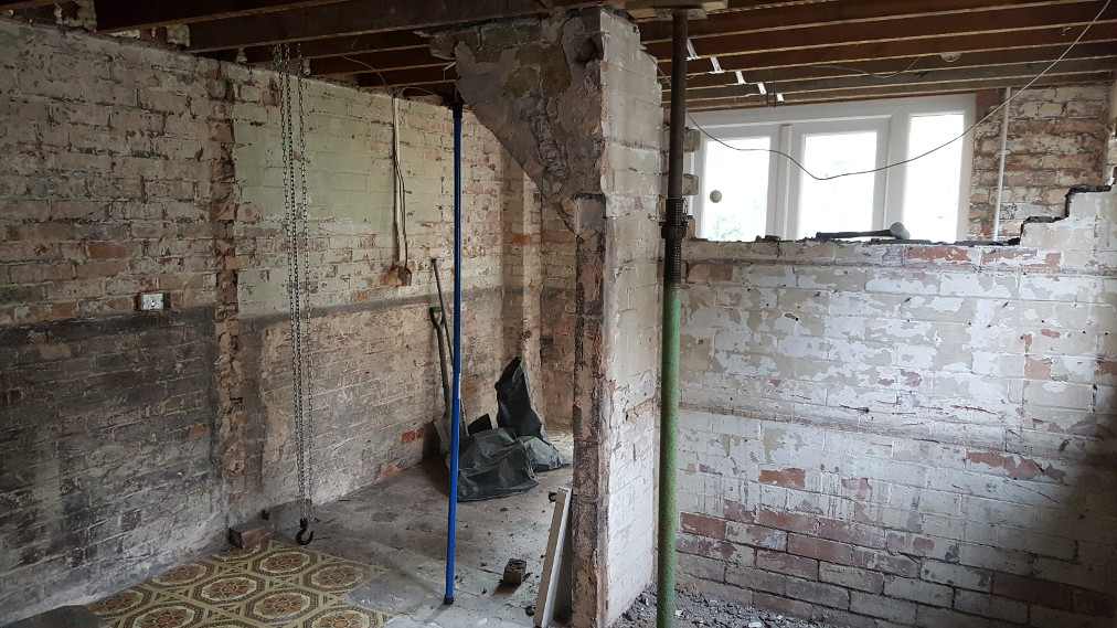
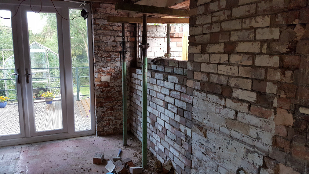
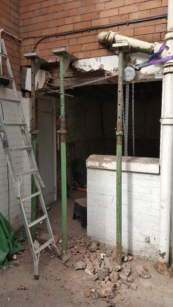
Part of the non load bearing wall removed. The heavy green jack in the fore ground is supporting the wooden beam that was holding the load bearing wall. The weight and load of the wall is now being supported on jacks which are out of shot. The blue prop is holding up the top of the triangular section of brick work. It was important to bring the wall down in a controlled manner for safety reasons.
Almost down. All of the bricks removed were saved for reuse later.
Last bit down and the dust yet to settle. The new steel joist can be seen in the background. The replacement joist was sized by a Structural Engineer and supplied, with all of the relevant certificates, by the local steel stockholders. The joist is cut to millilitre accuracy so does not require further cutting but the Building Controls people like to see it painted prior to installation and will, of course, have been notified prior to the work commencing. They will also require copies of the Structural Engineer's calculations and the steel certificates. I put all of this part of the work in the hands of Approved Inspectors Ltd who looked after all of the building controls work for me.
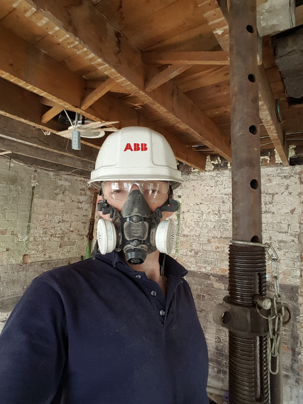
Always wear the appropriate PPE.
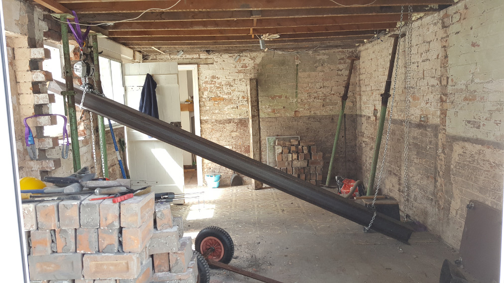
Raising the steel. The joist weighed 86kg in total so the weight wasn't too great and could probably have been lifted into place by four or five people but since I was doing the majority of the work on my own a more controlled approach was taken. Here I have raised on end of the beam up using a chain block and strops. This is so that the end of the joist is in the window hole as the length of the joist is around 200mm longer than the interior width of the room. The chain block on the right is supported on a frame on the floor above meaning that it is possible to lift the joist all the way up into place on its pad stone.
The other end of the joist couldn't be raised in this way as it was not possible to get a chain block above it so it was jacked into place using a pair of jacks to raise it in stages. The G clamps are being used to secure the jacks to the steel so that they don't slide and also to pull the non-lifting jack up behind. It looks complicated but the whole process of lifting the joist into place took around 45 minutes including setting up.
It's really important to plan the work and to think about how things are going to happen, what could go wrong and how to prevent this if the job is to be completed successfully and safely.
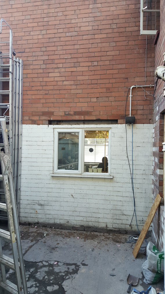
The new steel joist up in place. Note the props still supporting the joist as the pad stones have yet to be installed
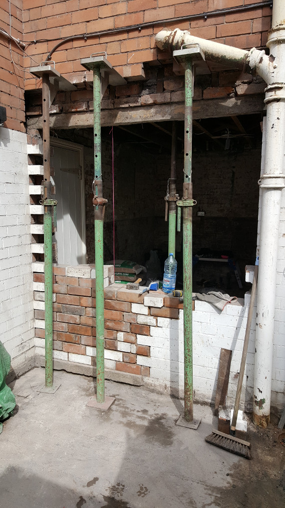
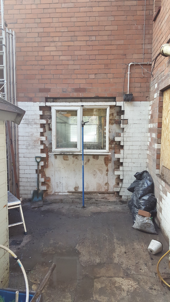
With the load bearing wall supported and the new steel in place it was time to open the window hole and rebuild the wall. Above is where we have 'toothed out' the old brick work from around the window (it was a total mess of broken bricks and mortar, the builder had relied on rendering the inside of the window hole to get an acceptable looking finish)
Using salvaged bricks from taking down the interior wall we then rebuilt the outer and inner leaves of the wall. The wall construction is called single brick so the inner and outer leaves of the wall are linked by cross bricks every few courses. On a small job like this it's worth dry laying the bricks so you know what order you're going to lay them and to allow you you cut any bricks that require cutting before hand.
Outer and inner leaves going up nicely. There isn't quite as much progress as it would appear, the outer leaf is just dry laid for the last few courses to keep out the weather over night.
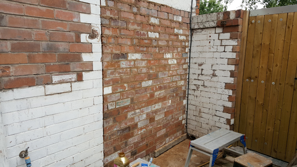
Good progress now, the wall actually looks pretty decent too!
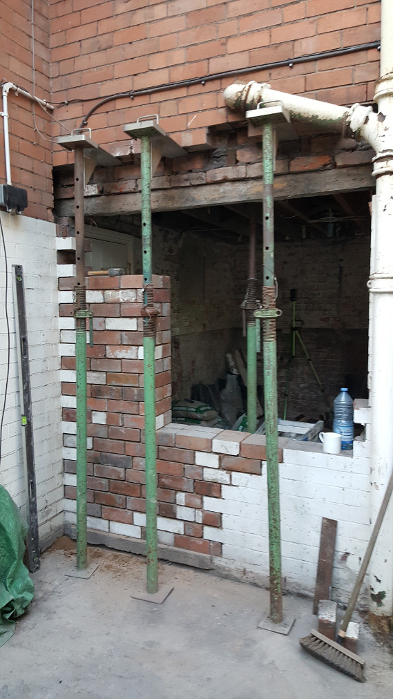
Once we'd completed building the wall to support the new steel it was on to the next bit of the job. The two small windows adjacent to the new brick work have been built in the wall where the old coal store and outside lavatory doors were. Neither wall was particularly well built and in the case of the nearer of the two was only a single thickness of brick. Neither piece of brick work was tied into the main wall either.
We struggled to remove the bricks in these pieces of wall as too much cement had been used in the mortar so the bond was too strong to split the bricks apart. Usually the mortar is weaker than than the bricks so that if there is any movement of the wall cracks appear in the mortar and the wall can move slightly. If the mortar is too strong then any movement will cause the bricks to fail: if this happens repairs are costly and time consuming as the wall has to be rebuilt rather than just repointed. Very few of the bricks from this part of the job could be salvaged as they broke during the demolition.
End of the day and the brickwork and the original pillar are gone. The original pillar was badly smashed about and we decided that it would be a better job overall if we took it out.
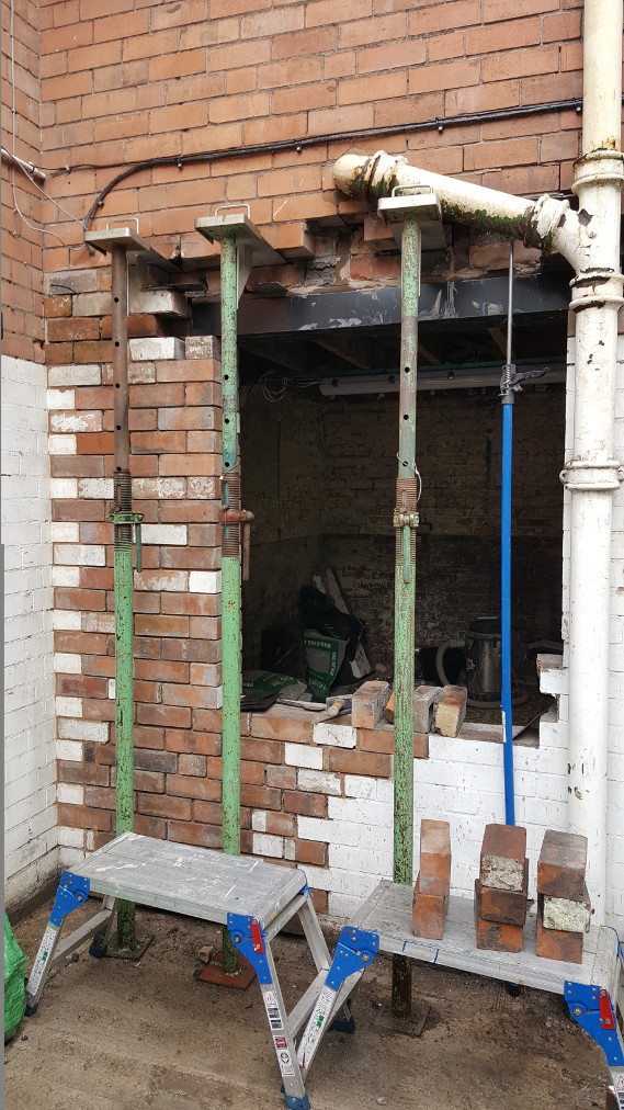
The original lintel is being supported as we weren't sure about the design strength of it (it is a 'cast in situ' lintel) and didn't want to have it crack as a result of us taking the pillar away from the middle.
Making a start on building the new piece of wall. We have fitted a wall starter kit to both sides of the opening which allows us to tie the new piece of brickwork into the existing brickwork either side. We have also inserted a damp proof membrane in line with the existing slate membrane but you can't see this because its under the bricks.
More brick laying. The hot weather caused some minor problems in that the mortar was drying out in the barrow (drying out as opposed to setting) so we had to cover the barrow with plastic to prevent evaporation. Nice problem to have though.
Shouldn't have moaned about the hot weather, the following day we got rain and I had to rig up a temporary cover to stop the mortar from getting too wet!
An inside view: as the wall got higher I had to alternate working from the inside and the outside as it wasn't practical to reach over the wall to lay the far leaf.
Finished apart from the last bit of pointing. The last few courses aren't quite as level as I would have liked but we were rushing to complete wall as we were due to go on holiday the following day.
The next task was to remove the cracked lintel from above the old kitchen door and window, replace the lintel, brick up part of the door way and build a new aperture for a French Window.
Here we've removed the door and the window frame. We rehung the door inside the house between the old kitchen and the rest of the house so that we had a bit more security and also to prevent too much dust blowing through. All of this kind of work creates huge amounts of dust and it seems to get right through the house despite our best efforts to keep it under control.
The tasks are gradually getting more complex and the level of preplanning required was intense.
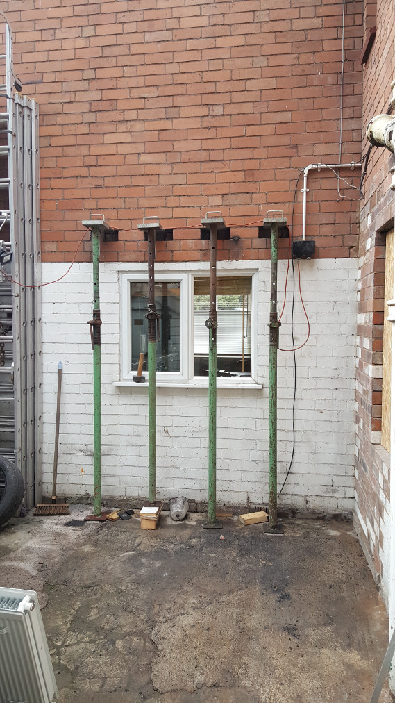
Stage one of supporting the wall above the lintel: Drilling out the mortar joints right through the wall and driving in the 'Strongboys'. These allow the wall to be propped from one side. It was not practical to support the wall in the way that we did with the other opening as, in this case we were completly removing the lintel to replace it, and it would have required the props to go through the floor above into the bathroom and the hallway.
We supported the ceiling joists from the inside with a spreader board and more props.
Ideally we'd have put another Strongboy in where the large white pipe comes down the wall but, because of this pipe, it was not practical to do so and we did end up with some minor cracking in the wall but this was dealt with by re-pointing later on in the job once the new lintel was in place.
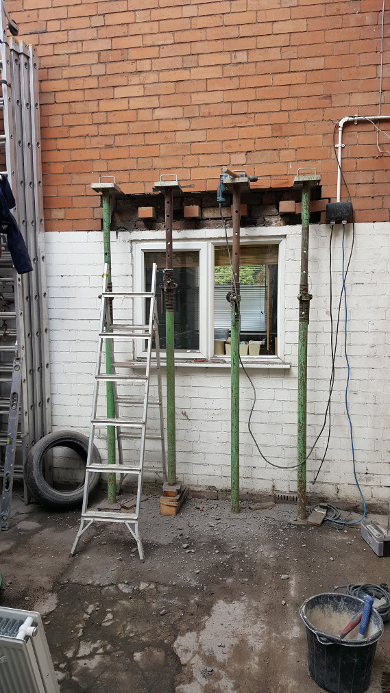
Props in place and demolition of the lintel commences. The lintel was a cast in situ lintel, i.e., it was formed by pouring wet concrete into a wooden formwork during the construction of the house. The qualify of some of the aggregates used in the concrete were not of the best which explains why is has cracked. That said it was a pretty massive chunk of concrete and we decided that it would be safer to break it up into pieces to remove it.
Using a chain block to draw the end of the lintel out of the brickwork. We did this to minimise the hammering on the existing, good wall and disrupting the brickwork. With a gentle pull from the chain block and some gentle wiggleing, we managed to remove it like a loose tooth.
Lintel out and the house is still standing.
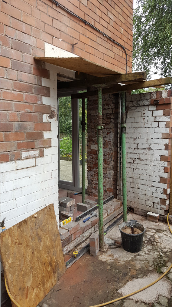
Starting construction of the new wall. The wooden beam in the picture was what was supporting the ends of the ceiling joists and the inner leaf of the wall. The load is currently being taken by the props on the inside of the building and, once the outer brickwork is at the right stage, the beam and the course of bricks above it will be replaced by the new lintel.
Window hole taking shape. If you look carefully, in the background, you can see my cross line laser. I set this up to save me having to check the line of the wall for 'plumb'. I just had to make sure that the 'perp' (the vertical end of the brick) lined up with the laser beam.
New lintel in place. This is 'Solid Wall Lintel' and is specifically designed for supporting the 'single' brick construction. There is a box section part at the inside with a slender flange protruding forward towards the outside of the wall. This means that the finished wall has a clean brick edged hole (as shown below) and the lintel is invisible.
Brickwork complete, awaiting final pointing.
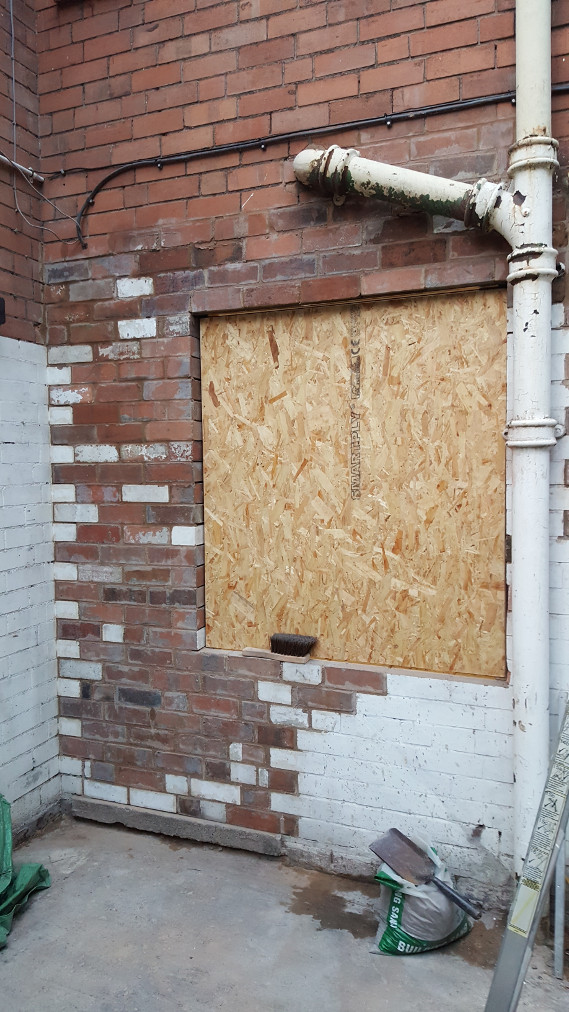
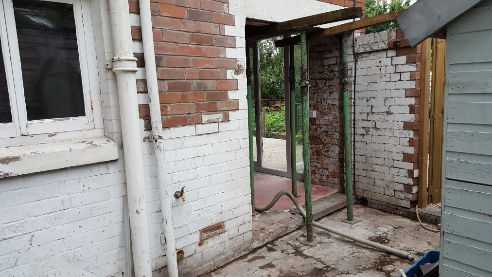
Temporary 'window'.
And on to the next bit! Here we're putting the props in, ready to fit a new, wider lintel slightly higher up on the wall as we're putting French Doors here to give access to the new kitchen from the yard.
Removing the bricks carefully as we don't want to damage the plaster board on the inside of the wall. The lintel is going in well ahead of the doors arriving and we didn't want to disrupt the new kitchen too much.
Checking the brick work for level prior to slotting the new lintel into the hole.
Difficult to see, but the new lintel is in the hole. With both this lintel and the other one we fitted there is a 20mm thick steel bar on top of the box section of the lintel. We did this so that the lintel fits in an exact number of courses of bricks so we didn't have to use 'Soldier Bricks' (2/3 bricks installed on end).
New lintel in place, ready for us to start making the door opening.
Nearly there with the opening. The blue prop is holding the window in place. The rain has arrived but the work goes on.
Building the reveals for the new door. Once these are complete the hole can be measured and the French Doors can be ordered. Whilst we wait for the doors the hole will be boarded up to keep out the weather.
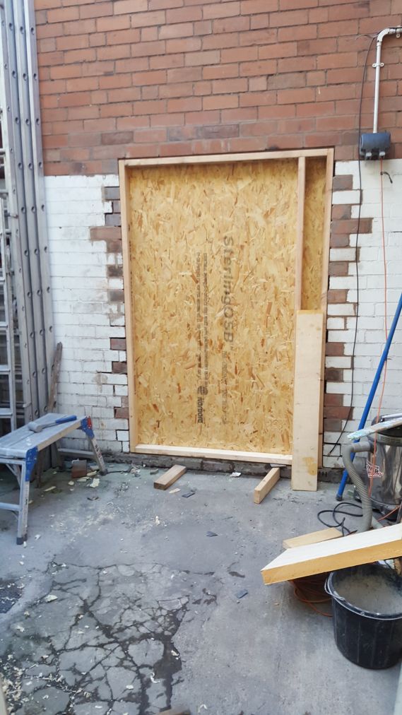
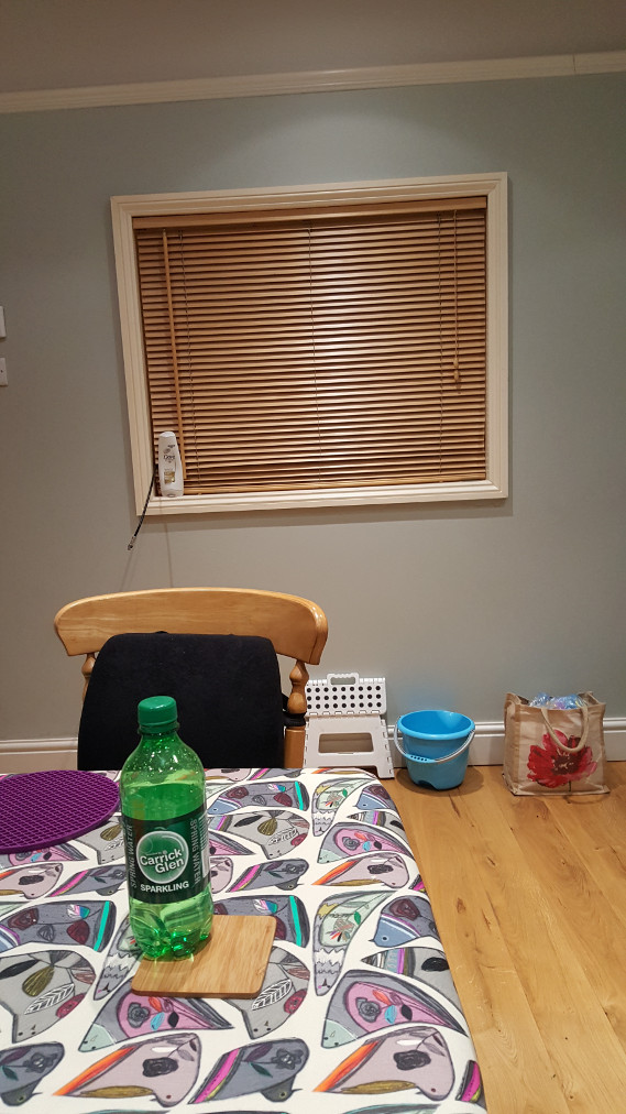
View from the inside. We left the blind up to hide the boarding.
On to the next task, digging up and replaceing the old kitchen and front room floors.
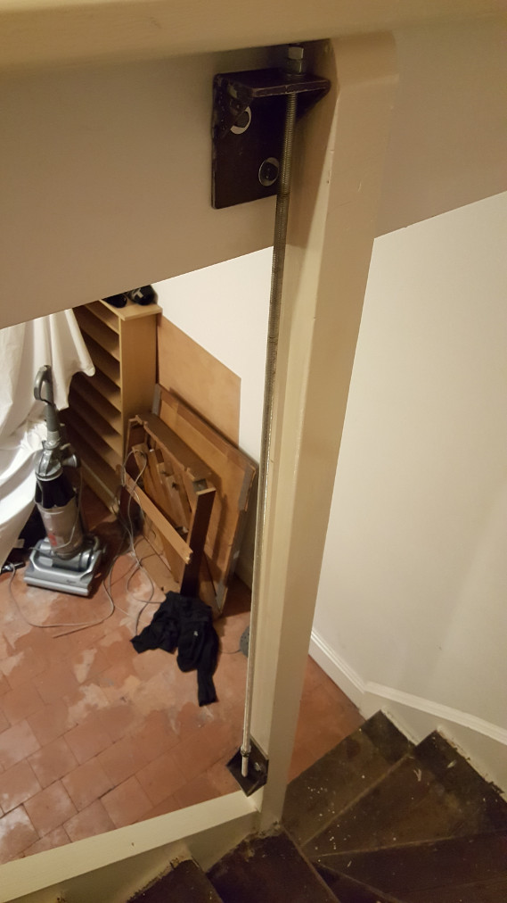
View of the iron work I made to support the bottom of the stairs whilst the floors are dug up.
At this point we took a back seat and let the builder get on with digging up the old, solid floors in the old kitchen and the front room.
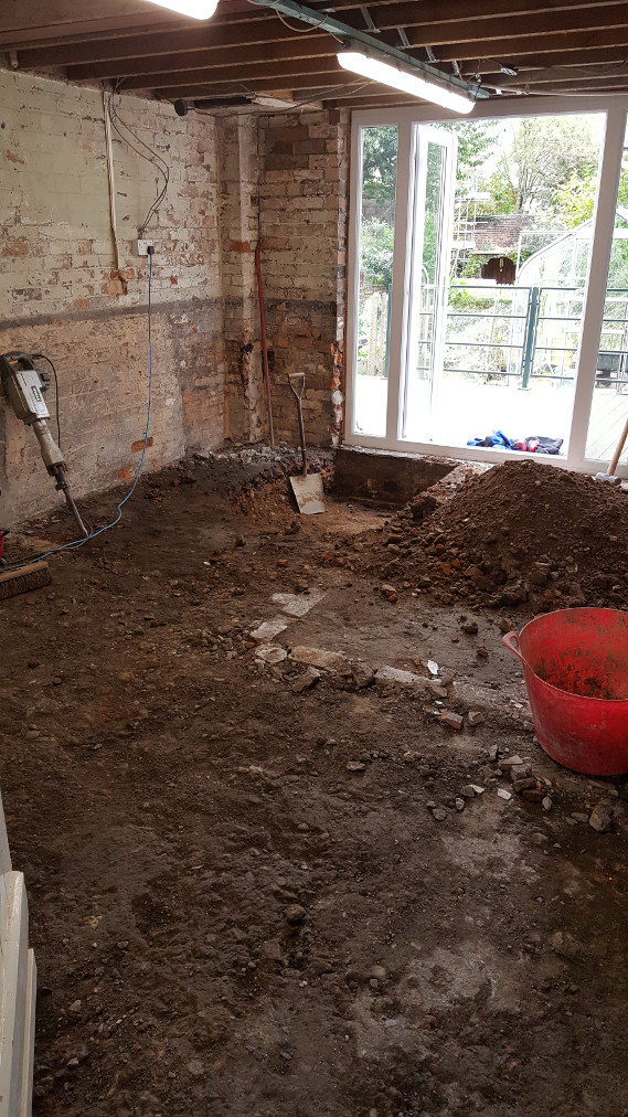
The end of day one and progress has been slow. All of the material being removed is carried out in the plastic builders skips like the red one in this picture. It's hard, heavy work and we were glad not be the ones doing it.
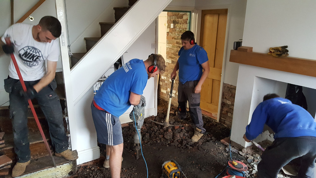
Plenty of muscle on the job today, six in this room and two more in the old kitchen tidying up.
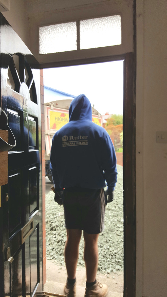
JJ watching the new stone for the subfloor arrive.
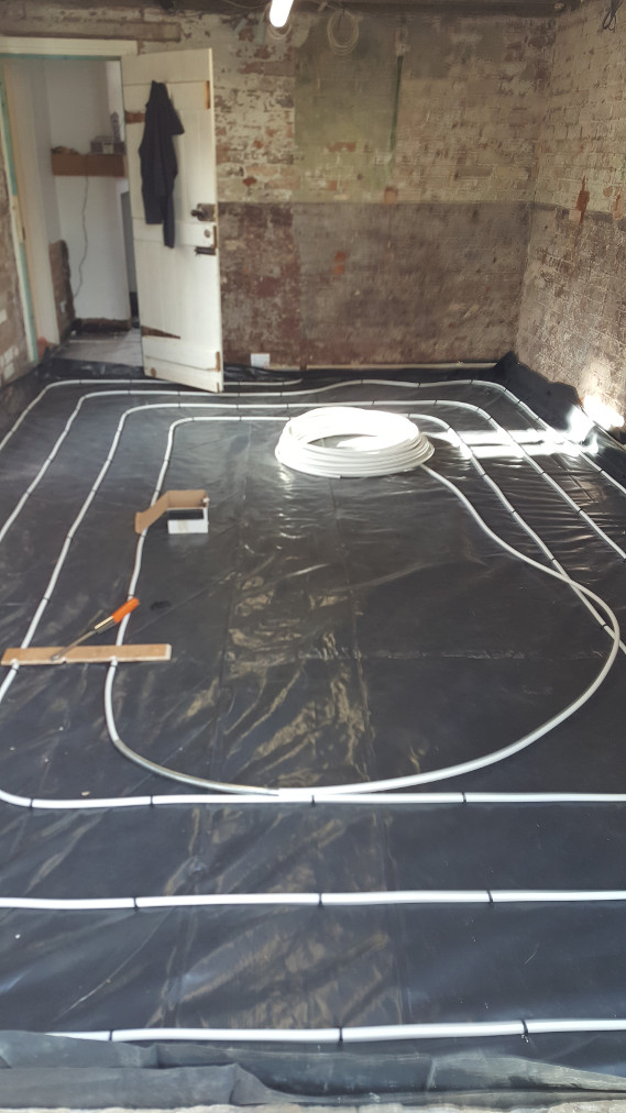
Five days later and the floors have been dug out, new subfloor has been installed, damp proof membrane has been installed, insulation has been installed with slip membrane on top. At this point the builders left, and we've made a start on the first underfloor heating circuit.
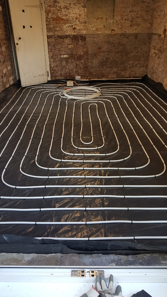
Completed heating circuit for the new living room.
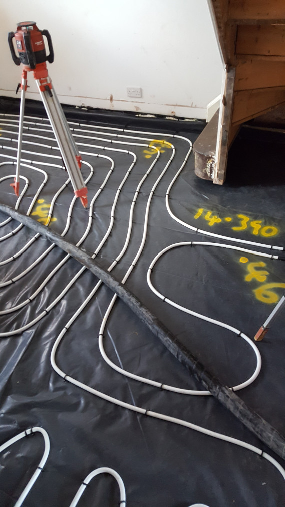
Circuit for the front room with the spot depths and the overall square meters sprayed on by the liquid screed installers.
The thick black pipe is what the liquid screed will be pumped through when they start installing the floor.

Concrete truck, pump and the installer.
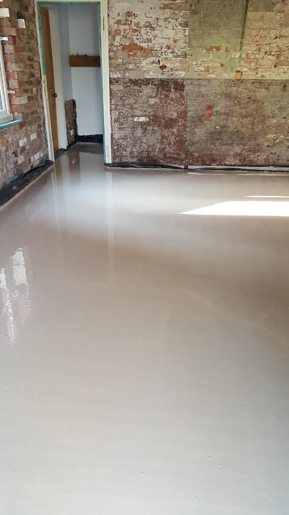
A sea of wet screed. Time for us to vacate the building for a couple of days whilst this sets. Drying out takes about a month and the floor can't be tiled until the humidity has dropped below a certain level. In our case this won't be a problem because it will be several months before we're at the tiling stage of the job.
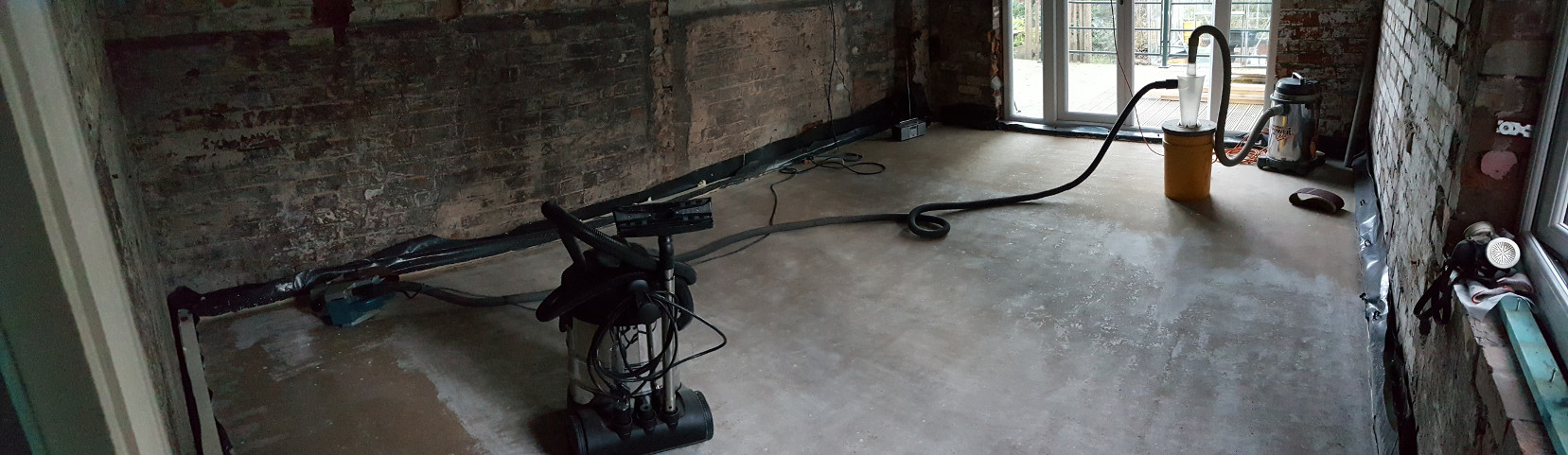
Once the screed has had about a week of drying the top surface laitance needs to be removed. The laitance is a thin, weak layer of screed caused by the very fine materials in the screed floating to the surface prior to the curing starting. The laitance can be scraped off (but it's very hard work) or ground off once the floor is dried out but for best results it is sanded off after the screed has cured as removing the laitance speeds up the drying process. (Screed, like concrete and cement, goes through a chemical reaction which causes it to set (Curing) followed by a slow process of drying out where the water used to promote the chemical reaction slowly evaporates)
Seen above is the set up I used: Makita Industrial Belt Sander linked to a cyclonic dust separator linked to a Seally Shop vacuum cleaner. The vacuum cleaner in the foreground is used for cleaning up the residual dust that remains on the floor from the sanding. The sanding on this floor is almost complete.
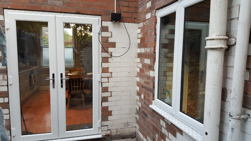
We ordered the French Window and Door just before the floor was pumped in and these arrived about two weeks later, in time for us to be ready to fit them. Since fitting them we've put the trim strips around them so you can't see the expanding foam. The strips were left off so that the building inspector could see that they had been sealed correctly.
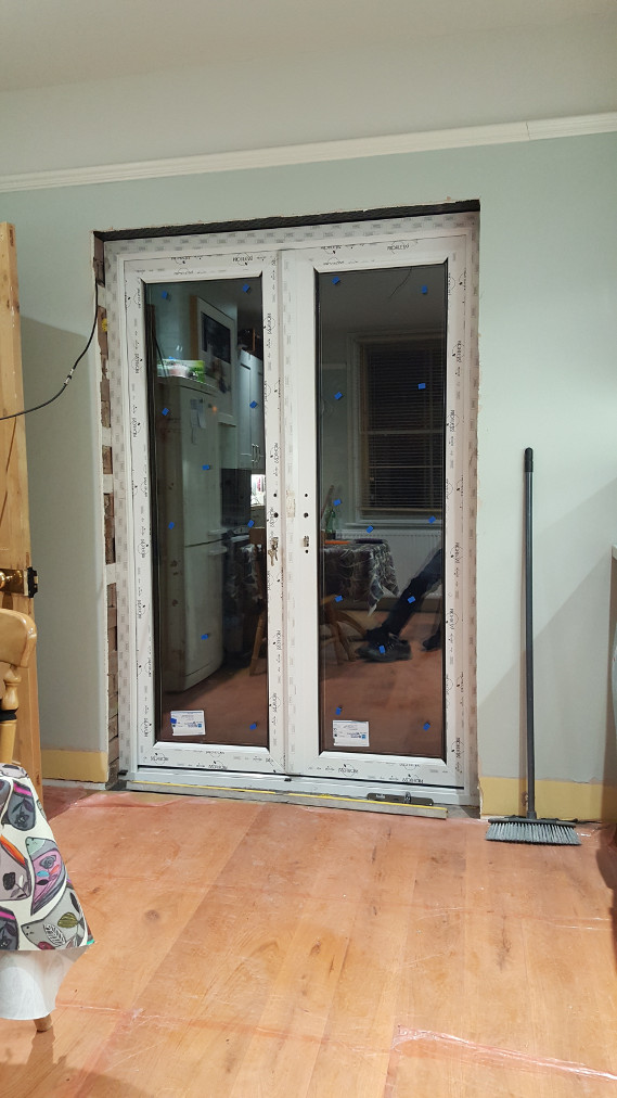
View from the inside.
As part of the renovation work we're installing insulated plaster board on all of the external walls. The kitchen had already been done when we gutted the room and replaced the rotting floor (see the original living room project) but we're now insulating all the other rooms.
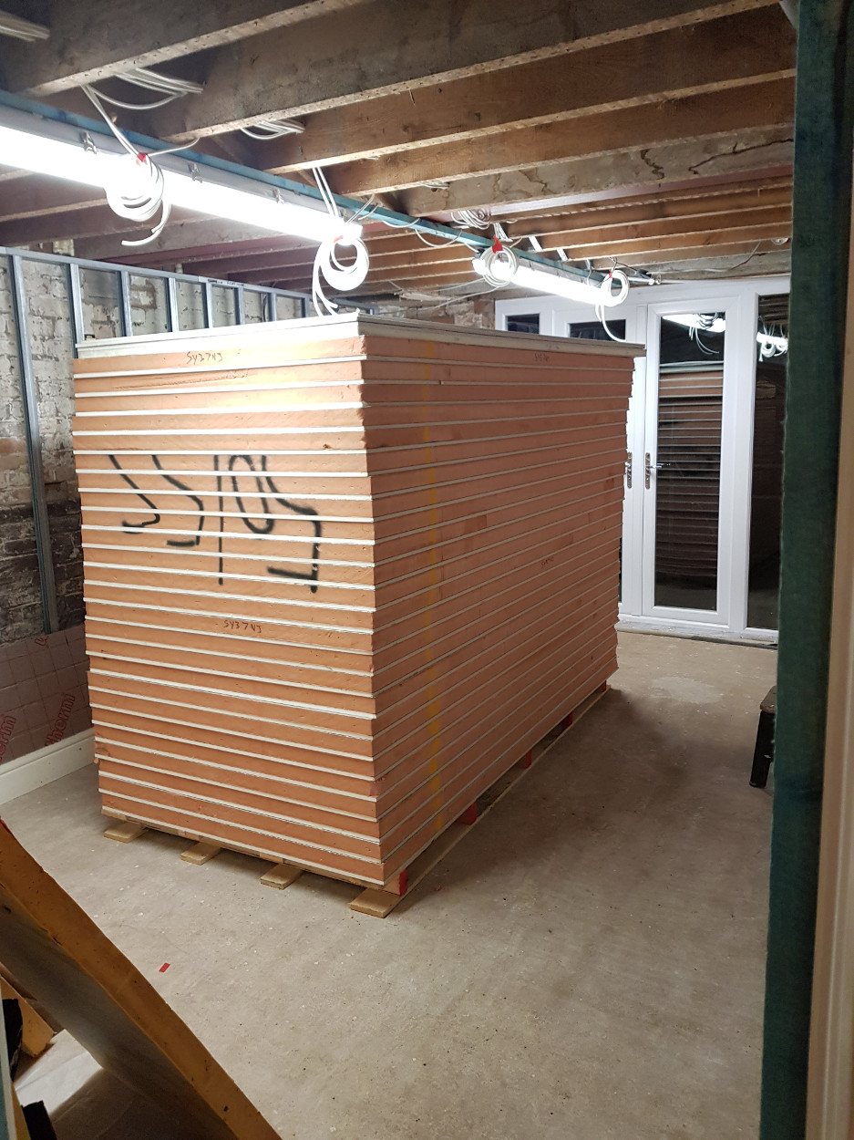
Over £1200 worth of Kingspan insulated plaster board, waiting for us to install it.
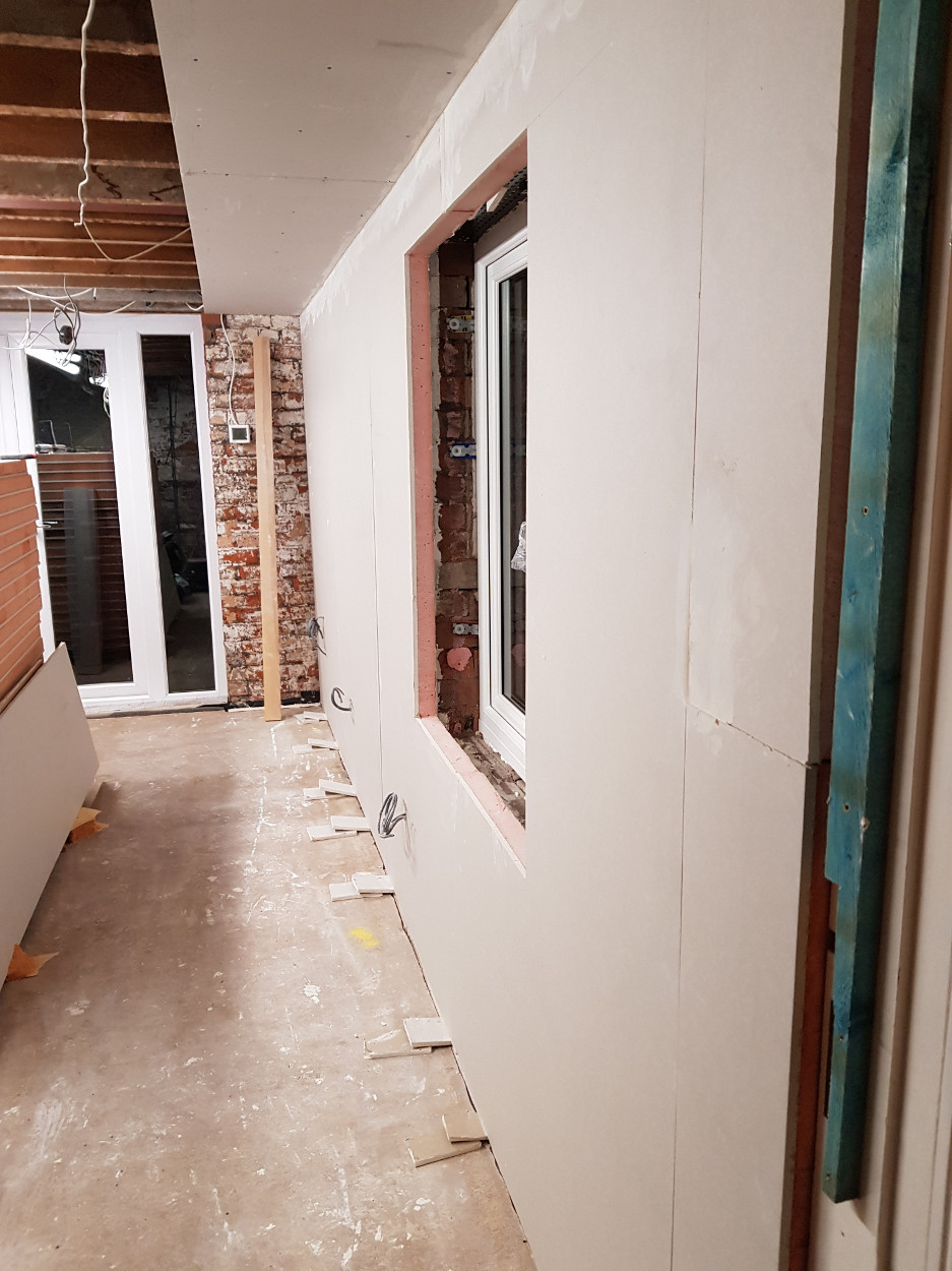
Making a start on the long wall.
On the party wall we are installing sound proofing. We've never had really noisy neighbours but the house next door is rented and there is always the chance we'll end up with an inconsiderate neighbour. (or one who doesn't share our taste in Folk, Celtic Punk Rock or Classic Rock music)
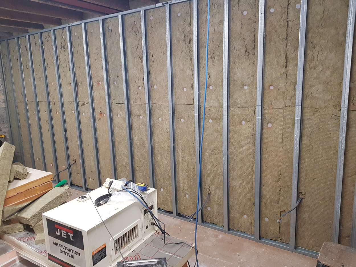
The party wall showing the Rockwool RWA45 sound installation (75mm thick) and the British Gypsum acoustic stud wall system. Also in this picture one of the two Jet Air Filtration Systems that I bought in order to reduce the dust level (They work very well)
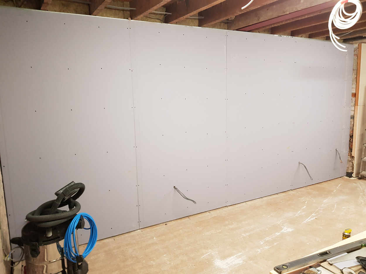
The acoustic stud wall clad in BG Soundbloc 15 mm plaster board. This board is nearly twice as dense as normal plasterboard and weighs around 46kg per 1.2x2.4 m sheet!
In the front room, because of the stairs, we couldn't use this type of construction and have instead used a less effective but slimmer system.
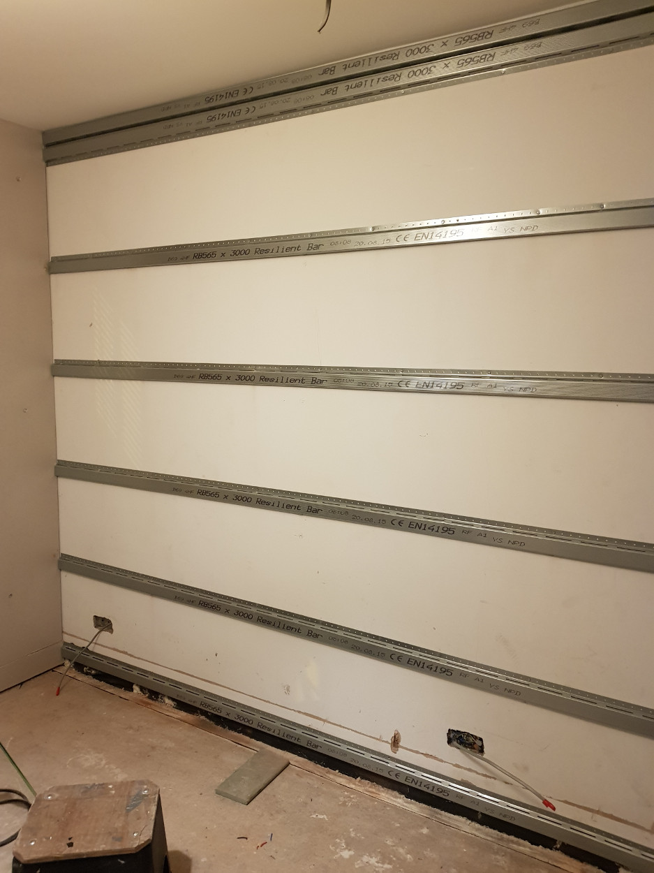
In this case we've used
'Resilient Bar' which is very lightweight, springy steel battening which is
fixed along one edge only. The Soundbloc plaster board is then fitted to this
and the edges and joints are completely sealed with acoustic sealant. This system
adds about 30-35mm to the wall so is not too intrusive. There are options for
increasing the sound deadening capabilities of the wall by adding a polymer
sheet under a second layer of standard plasterboard or a further layer of soundbloc
board. We'll try it out with the single layer first.
At the end of this project,
after a few months of lieing idle, we sold off the acro jacks, the Strongboys
and one of the Jet air filtration units as we had no future use for them and
they took up a lot of space.